
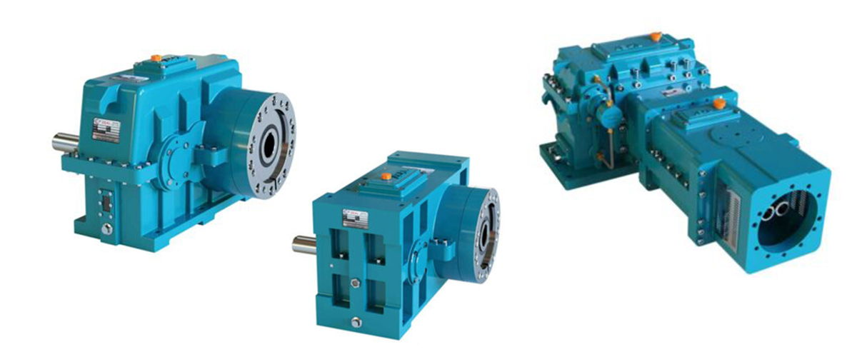
A plastic extruder gearbox is one of the most reliable mechanical components in industrial manufacturing — but only when it receives the maintenance it needs, at the intervals it needs it, performed correctly and completely. Skip the monthly oil check and you miss the early signs of gear wear. Delay the annual oil change and the degraded lubricant accelerates damage to every component it touches. Forget the three-yearly bearing inspection and you discover the bearing’s condition only when it fails during a production run. This complete maintenance checklist has been developed specifically for plastic extruder helical gearboxes and covers every maintenance task from the 2-minute daily shift check through the 3 to 5-year major overhaul. It is organised by frequency — each section contains only the tasks due at that interval, with clear instructions on how to perform each check, what a healthy result looks like, and what action to take when the result is outside acceptable limits. Every checklist section is formatted as a printable table that your maintenance team can use directly in the field. The goal of this document is simple: to give every maintenance team, shift supervisor, and plant engineer a single, complete reference that covers everything they need to do to keep their extruder gearboxes running reliably for their full service life — without needing to consult multiple manuals, search through archived documents, or rely on institutional memory that leaves with experienced staff. Implement this checklist consistently and your gearboxes will reward you with years of trouble-free production.
How to Use This Maintenance Checklist
This checklist is structured to be used in two ways: as a reference guide that explains why each task matters and how to perform it correctly, and as a set of printable field checklists that maintenance technicians can physically tick off as each task is completed. Both uses are equally important — understanding the rationale behind each task leads to better execution, and the physical act of ticking a checklist item drives accountability and creates a maintenance record.
- Assign Ownership: Each checklist frequency should have a named responsible person or role — shift supervisor for daily checks, maintenance technician for weekly and monthly checks, maintenance engineer for quarterly and 6-monthly checks, and a senior engineer for annual and beyond.
- Print and Use in the Field: Each checklist section is designed as a standalone printable table. Print a fresh copy for each period, complete it during the maintenance task, sign it, and file it in the machine maintenance record. This creates an auditable maintenance history that is invaluable when diagnosing developing problems.
- Record Results, Not Just Completion: Do not just tick a box — record the actual measured value wherever applicable (oil temperature reading, motor current percentage, axial play measurement). Trend data from recorded values is far more valuable than a series of ticks.
- Act on Findings Immediately: A checklist item that returns an out-of-range result is not complete until the appropriate action has been taken and documented. The checklist is not done when the observation is made — it is done when the response is executed.
- Keep All Completed Checklists: File every completed checklist in the machine maintenance folder. These records are your most valuable diagnostic resource when a problem develops, providing the historical context needed to distinguish a developing trend from a one-off anomaly.
Maintenance Schedule Overview – All Tasks at a Glance
The following master schedule table lists every maintenance task with its frequency, responsible party, estimated time, and the section of this guide where full details are found. Use this as your master planning reference for scheduling maintenance resources.
| Frequency | Task Summary | Responsible | Time Required | Section |
| Every Shift | Oil level, temperature, noise, cooling water, leaks, motor current | Shift Supervisor | 2 – 4 min | Checklist A |
| Weekly | Vibration feel, coupling inspection, housing scan, breather check | Maintenance Tech | 8 – 12 min | Checklist B |
| Monthly | Oil sample + visual, drain plug magnet, housing clean, IR thermometer scan | Maintenance Tech | 15 – 25 min | Checklist C |
| Quarterly (3M) | Oil condition assessment, breather replacement, bolt torque check | Maintenance Engineer | 20 – 30 min | Checklist D |
| 6-Monthly | Spectrometric oil analysis, vibration measurement, axial play check | Maintenance Engineer | 30 – 45 min | Checklist E |
| Annual (12M) | Full oil change, shaft alignment, seal inspection, cooling coil check | Senior Engineer | 3 – 6 hours | Checklist F |
| 3-Year | Major inspection: gears, bearings, seals, housing, cooling system overhaul | Senior Engineer + OEM | 1 – 2 days | Checklist G |
| 5-Year | Full gearbox overhaul: disassembly, measurement, component assessment | OEM / Specialist | 2 – 4 days | Checklist H |
Essential Tools and Materials for Gearbox Maintenance
Before beginning any maintenance task, confirm that the required tools and materials are available. Attempting maintenance without the correct tools leads to incomplete or incorrect execution that can cause more harm than no maintenance at all.
Tools Required
| Tool | Use in Gearbox Maintenance | When Required |
| Calibrated torque wrench (set) | Tightening housing bolts and drain plugs to specified torque | Monthly, Annual, Post-maintenance |
| Infrared (IR) thermometer | Non-contact temperature measurement at housing surface points | Weekly and Monthly |
| Dial indicator with magnetic base | Measuring output shaft axial play accurately | 6-Monthly and Annual |
| Oil sample bottles (clean, sealed) | Collecting oil samples for visual and laboratory analysis | Monthly and 6-Monthly |
| Calibrated vibration meter | Measuring and recording vibration amplitude at defined points | 6-Monthly |
| Laser shaft alignment tool | Verifying motor-to-gearbox shaft alignment precisely | Annual |
| Feeler gauge set | Checking coupling alignment gap and parallelism | Annual |
| Container for oil drainage (clean) | Collecting drained oil for disposal — must be clean to avoid contamination | Annual oil change |
| Funnel and oil transfer pump | Filling gearbox with new oil cleanly without spillage | Annual oil change |
| Cleaning cloths (lint-free) | Wiping housing surfaces and components during inspection | All tasks |
| Inspection torch / UV light | Examining seal areas, housing joints, and drain plug area | Monthly and beyond |
| Vernier caliper or micrometer | Measuring shaft diameters and wear at annual inspection | Annual and 3-Year |
Consumables to Stock
- Gear Oil (correct grade and type): Keep minimum 2x the gearbox oil capacity in stock at all times. Never be caught without oil during a planned change.
- Shaft Seals (FKM / Viton): Keep one complete set of input and output shaft seals in stock. Seals are cheap; downtime waiting for them is expensive.
- Cooling Coil Descaling Agent: Appropriate chemical descaler for the coil material (copper-nickel or stainless). Keep one supply available.
- Breather Filter Elements: Keep two replacement breather elements in stock per gearbox. Replace annually or when blocked.
- Oil Analysis Sample Bags / Labels: Pre-labelled, clean oil sample bottles from your chosen laboratory. Prevents contamination of the sample.
- Liquid Gasket Compound: For resealing the housing split joint at annual maintenance. Use manufacturer-specified product only.
- Lint-Free Cleaning Cloths and Solvent: For housing surface cleaning during inspection. Keep a regular supply.
CHECKLIST A — Daily Shift Checks
Frequency: Every 8 to 12 hour shift | Responsible: Shift Supervisor | Time: 2 to 4 minutes
These checks are performed at the beginning of each shift and take under 4 minutes. They require no tools and no machine stoppages. The objective is to detect any change from normal that warrants investigation before it becomes a problem. All readings should be recorded in the machine maintenance log — not just noted and forgotten.
| # | Check Task | Method | Normal / Pass Result | Action if FAIL |
| A1 | Oil level — check sight glass or dipstick | Visual — stop machine briefly if dipstick check | Between MIN and MAX marks | Top up with correct grade; investigate if level drops frequently |
| A2 | Oil temperature — read sump thermometer or gauge | Read and record the displayed value | 40 – 75°C (record actual reading) | Check cooling water; investigate if above 80°C |
| A3 | Cooling water flow — confirm outlet pipe is warm | Touch outlet pipe gently during operation | Noticeably warm vs inlet | Check water supply valve; check pump flow |
| A4 | Listen to gearbox during startup and running | Listen for new or changed sounds | Smooth, steady, consistent hum | Log the change; assess urgency by sound type |
| A5 | Visual check — oil on floor or housing surface | Walk around gearbox; check floor and housing | No new staining or drips | Locate source; log; plan repair |
| A6 | Motor current — read VSD display | Read and record % of rated current on VSD | Within normal range for material | Investigate if >10% above baseline for same conditions |
| A7 | Product quality — check current run for dimensional variation | Observe extrudate or check last dimension record | Consistent with specification | Correlate with gearbox data; investigate drive system |
Daily Shift Log — What to RecordRecord the following in the machine log at each shift handover:
Date and time:
Oil temperature reading (°C):
Motor current reading (% rated):
Oil level (OK / Low / Topped up):
Any noise change (Yes / No — describe if Yes):
Any leakage (Yes / No — location if Yes):
Any product quality issue (Yes / No):
Shift supervisor signature:
CHECKLIST B — Weekly Checks
Frequency: Every 7 days | Responsible: Maintenance Technician | Time: 8 to 12 minutes
Weekly checks expand on the daily observations and include the first level of physical inspection — vibration feel, coupling condition, and housing thermal scanning. These checks take under 15 minutes and should be scheduled on the same day each week to maintain consistency.
| # | Check Task | Method | Normal / Pass Result | Action if FAIL |
| B1 | Vibration feel — place hand flat on housing at 4 points | Palm flat on: input end, output end, top, sides | Smooth, uniform low vibration at all points | Note any high-vibration zone; compare next week; see Checklist C |
| B2 | Coupling visual inspection — check flexible element | Remove coupling guard briefly (machine OFF); inspect visually | No cracking, tearing, or rubber dust | Log condition; plan replacement if cracking present |
| B3 | Housing surface temperature scan — IR thermometer at 6 fixed points | Record temperature at same 6 points each week | Uniform; within ±5°C of last week at each point | Hot spot developing: investigate location; check oil level |
| B4 | Breather vent — confirm not blocked | Visual check; gently poke with wire if dusty environment | Free airflow; no dust blocking | Clean or replace breather filter element |
| B5 | Cooling water inlet temp — confirm below 35°C | Thermometer or feel on inlet pipe (cold to touch) | Below 35°C on inlet | Investigate cooling tower; check chiller if fitted |
| B6 | All visible external housing bolts — confirm no obvious looseness | Visual check; tap with wrench handle — ring = tight, dull = loose | No loose or missing bolts | Retighten with torque wrench to specified torque |
| B7 | Oil sight glass — check oil colour as well as level | Observe colour in sight glass against good light | Clear amber; level between marks | Dark or milky colour: elevate to monthly oil sample |
CHECKLIST C — Monthly Checks
Frequency: Every 30 days | Responsible: Maintenance Technician | Time: 15 to 25 minutes
Monthly checks introduce the oil sample — both visual inspection and drain plug examination — which provides the most direct window into gearbox internal condition. These checks require a brief machine stop for the drain plug and oil sample tasks, and should be scheduled at a natural production changeover or material break where possible.
| # | Check Task | Method | Normal / Pass | Action if FAIL |
| C1 | Drain 100 ml oil sample for visual inspection | Clean jar; drain from sump drain cock or dipstick tube | Clear amber; no particles or cloudiness | Milky = Stop (water ingress). Dark = plan early change |
| C2 | Inspect magnetic drain plug for metallic particles | Remove drain plug (machine OFF and cooled); clean magnet on white cloth; photograph | Very fine grey powder only | Flakes or bronze = Level 2. Large fragments = Level 4 (Stop) |
| C3 | Clean housing external surfaces and cooling fins thoroughly | Brush or compressed air to remove polymer dust and plastic fines | Clean fin surfaces; no dust mat | Temperature typically drops 3–8°C after thorough cleaning |
| C4 | Check output shaft seal area for seepage (clean then recheck) | Clean area; run machine 20 min; recheck for fresh oil | Completely dry after cleaning | Any seepage = plan seal replacement at Annual check |
| C5 | Check input shaft seal area (motor coupling side) | Same clean-and-recheck method as C4 | Completely dry after cleaning | Seepage = plan repair; check motor shaft alignment |
| C6 | Record trend data from daily log for the month | Review all daily log entries; compute average temp and current | Stable trends; no rising patterns | Rising temp or current trend = elevate to 6-monthly check |
| C7 | Check cooling water circuit connections for scale or drips | Visual inspection of all water inlet, outlet, and valve fittings | No scale deposits; no drips at connections | Scale: plan descaling. Drips: tighten or replace fittings |
| C8 | Verify correct oil grade label is displayed on gearbox | Check the oil type label matches the specified grade | Label present and matching specification | If incorrect grade was added: change oil immediately |
Drain Plug Magnet — What the Particles Tell You
Very fine grey powder (barely visible) → Normal baseline wear — no concern
Thicker layer of fine powder than last month → Wear rate increasing — take oil sample for lab analysis
Silvery grey flakes (visible individually, 0.5 – 3 mm) → Gear or bearing surface damage — Level 2 investigation
Large fragments (> 3 mm) → Major component fracture — Level 4: Stop machine, inspect gearbox
Bronze / gold coloured particles → Bronze cage or worm wheel wear — identify and inspect source
Always photograph the drain plug before cleaning — the photo becomes your trend record.
CHECKLIST D — Quarterly Checks
Frequency: Every 3 months | Responsible: Maintenance Engineer | Time: 20 to 30 minutes
Quarterly checks build on the monthly results and add a more detailed assessment of oil condition, hardware tightness, and environmental factors. At this frequency, the maintenance engineer is reviewing not just individual check results but the three-month trend in all daily and monthly records.
| # | Check Task | Method | Normal / Pass | Action if FAIL |
| D1 | Oil condition assessment — colour, smell, and texture | Drain 200 ml sample; assess colour, smell, and texture on gloved finger | Clear amber; no acid smell; fluid texture | Darkened, sour-smelling, or thickened oil = early oil change |
| D2 | Replace or clean breather filter element | Remove breather; inspect element; clean with solvent or replace | Clean mesh; free airflow through element | Blocked element = replace; blocked vent causes seal failure |
| D3 | Full torque check of all housing bolts | Torque wrench to manufacturer specification on all housing bolts | All bolts at specified torque (no movement) | Retighten any loose bolts; check thread condition |
| D4 | Check and record ambient temperature near gearbox | Thermometer at housing level during peak production | Below 45°C for standard application | Above 45°C: review cooling system adequacy; consider PAO oil |
| D5 | Review 3-month trend in daily log data | Plot or review temperature and current readings from last 3 months | Stable or within ±5°C and ±5% current | Rising trend: investigate root cause; elevate frequency |
| D6 | Check VSD parameter settings have not drifted | Review VSD max frequency, current limit, and ramp settings | All parameters at commissioning values | Unauthorised changes: restore to design values and investigate |
| D7 | Check motor-to-gearbox coupling alignment qualitatively | Check parallel gap at 4 points on coupling rim with feeler gauge | Gap consistent within ±0.3 mm around circumference | Gap variation > 0.5 mm = re-align coupling |
CHECKLIST E – 6-Monthly Checks
The 6-monthly check introduces the two most powerful condition monitoring tools available for extruder gearboxes: laboratory oil analysis and vibration measurement. Both provide early warning of developing problems that are not yet visible to any other check — giving maximum time for planned, cost-effective intervention before failure occurs.
| # | Check Task | Method | Normal / Pass | Action if FAIL |
| E1 | Send oil sample to laboratory for spectrometric analysis | 100 ml clean sample in pre-labelled bottle to accredited lab | Within limits for all parameters — see table below | Review trend with lab; increase check frequency; plan oil change if borderline |
| E2 | Vibration measurement at defined housing points | Calibrated vibration meter at 4 to 6 fixed points; record amplitude | Within ±20% of baseline for each point | Rising amplitude: trending report; schedule inspection |
| E3 | Measure output shaft axial play with dial indicator | Dial gauge on shaft end; push and pull firmly; record total movement | 0 – 0.15 mm (within design clearance) | Rising play: plan thrust bearing inspection at Annual |
| E4 | Check and record motor insulation resistance (megger test) | Qualified electrician tests motor winding insulation with megger | Above 1 MΩ at 500V DC test | Falling insulation: inspect motor windings; check for moisture |
| E5 | Inspect coupling flexible element closely | Remove guard; inspect element at ×2 magnification for hairline cracks | No cracks; uniform rubber; no permanent set | Any crack = replace at next convenient stop (Level 2) |
| E6 | Check oil level under load (machine running) | Observe sight glass during normal production | Level maintained between marks under load | Level drops under load: investigate internal oil consumption |
| E7 | Inspect housing surface for new cracks or paint damage | Full visual inspection of all housing surfaces with torch | No cracks; no new damage; paint intact | Any crack: NDT assessment; plan repair or replacement |
| E8 | Verify cooling coil water flow rate | Measure flow with flow meter at coil outlet or time bucket fill | At design flow rate (from commissioning data) | Low flow: flush circuit; check pump; inspect for scale |
Oil Analysis — Parameters to Request and Normal Limits
Parameter | Baseline (new oil) | Caution Level | Action Level
——————–|——————–|———————–|——————–
Viscosity @ 40°C | Grade nominal ±10% | ±15% of nominal | ±20% — change oil
Acid Number (mg KOH/g)| < 0.5 | 1.0 – 1.5 | > 2.0 — change oil
Iron (Fe) ppm | < 10 ppm | 50 – 100 ppm | > 150 ppm — inspect
Chromium (Cr) ppm | < 5 ppm | 20 – 40 ppm | > 60 ppm — inspect
Water content (ppm) | < 200 ppm | 500 – 1,000 ppm | > 1,000 ppm — investigate
Silicon (Si) ppm | < 10 ppm | 30 – 60 ppm | > 80 ppm — check seals
Copper (Cu) ppm | < 10 ppm | 40 – 80 ppm | > 100 ppm — check coil
Particle count (ISO 4406)| ≤ 18/16/13 | 20/18/15 | > 22/20/17 — filter/change
Always compare to the PREVIOUS sample result — trend is more important than absolute value.
CHECKLIST F — Annual Maintenance
Frequency: Every 12 months | Responsible: Senior Engineer | Time: 3 to 6 hours (planned shutdown)
The annual maintenance is the most comprehensive routine maintenance event for the extruder gearbox. It requires a planned production shutdown of sufficient duration to allow all tasks to be completed properly. Do not rush the annual maintenance — the tasks performed here directly determine the gearbox’s reliability for the next 12 months of production.
Pre-Maintenance Preparation
- Confirm oil grade and quantity: Verify the correct grade is in stock. Calculate the exact fill volume from the gearbox datasheet.
- Assemble all tools and consumables: All items from Section 3 should be available before the shutdown begins.
- Notify production: Confirm the shutdown window with production management — minimum 4 hours for a complete annual service.
- Isolate the machine safely: Lockout/tagout procedure on motor supply before starting any maintenance. Never work on a gearbox that is not fully isolated.
| # | Annual Maintenance Task | Procedure Summary | Pass Criterion | Action if FAIL |
| F1 | Full oil drain and flush | Drain hot oil (run machine for 10 min first to warm oil; then stop and drain immediately while warm) | Complete drainage; clean sump | Flush with small amount of new oil; drain again |
| F2 | Sump interior inspection | Torch inspection through drain opening or inspection cover for sludge, varnish, or debris | Clean interior; no sludge buildup | Clean sump interior with clean solvent cloths before refilling |
| F3 | Magnetic sump plug inspection and cleaning | Clean magnet; photograph particles; reinstall with new sealing washer and correct torque | Very fine powder only at annual | Significant particles: escalate to 3-Year inspection |
| F4 | Fill with new oil to correct level | Pour through clean funnel to specified fill level; use correct grade only | Level between marks on sight glass | Overfill or underfill: drain or add to correct level |
| F5 | Replace both shaft seals (input and output) | Remove old seals; clean shaft and housing bore; fit new FKM seals with correct orientation and depth | Seals seated correctly; no damage | Incorrect fitting: remove and refit — never force a seal |
| F6 | Inspect old seals for failure mode evidence | Examine removed seals: hardened lip = overheating; abraded lip = contamination ingress | Note failure mode; address root cause | Hardened = improve cooling. Abraded = fit secondary seal |
| F7 | Verify shaft alignment (laser alignment tool) | Full laser alignment check on motor-to-gearbox and gearbox-to-extruder shaft couplings | Parallel offset < 0.05 mm; angle < 0.03° | Re-align; repeat check; document final alignment values |
| F8 | Inspect and clean cooling coil (if accessible) | Flush water side with descaling agent; check coil surface for corrosion; verify coil integrity | Clear bore; no corrosion; no leaks | Corrosion: assess condition; replace coil if perforated |
| F9 | Replace breather filter element | Remove old element; fit new element of correct size and rating | New element fitted; vent free-flowing | Check breather is correct rating for environment |
| F10 | Check all housing bolts for correct torque | Torque wrench to specified value on ALL housing fasteners | All bolts at specified torque | Replace any damaged threads with thread insert |
| F11 | Inspect and test thermostat (if fitted) | Verify thermostat opens at specified temperature using hot water bath test | Opens within ±3°C of setpoint | Replace faulty thermostat before restarting |
| F12 | Run machine after service and verify all normal | Start machine; allow 30 min at normal load; check all daily check parameters | All daily checks pass | Investigate any anomaly before returning to production |
| F13 | Update maintenance record and label gearbox | Record oil grade, quantity, date, and next service date on gearbox service label and log | Records complete and filed | — |
CHECKLIST G – 3-Year Major Inspection
Frequency: Every 3 years | Responsible: Senior Engineer + OEM Support | Time: 1 to 2 days
The 3-year major inspection is the first opportunity to inspect the internal components of the gearbox directly — the gear tooth surfaces, bearing condition, shaft journals, and housing geometry — without necessarily fully disassembling the unit. It requires a planned shutdown of one to two days and should be scheduled during a planned production maintenance period.
| # | 3-Year Inspection Task | What to Look For and Record | Action if Issue Found |
| G1 | Remove inspection cover(s) and internal borescope inspection | Gear tooth flanks: pitting, scoring, or wear pattern changes. Bearing surfaces visible through openings | Pitting > 4% tooth area: plan gear replacement. Scoring: investigate lubrication |
| G2 | Measure and record output shaft axial play | Dial indicator: total axial movement under firm axial force. Record and compare to baseline and previous measurement | Play > 0.4 mm: plan thrust bearing replacement before next year |
| G3 | Measure input shaft radial play (bearing clearance) | Dial indicator at input shaft with indicator tip against shaft surface; lift shaft; record total movement | Play > 0.2 mm: input bearing wear — plan replacement |
| G4 | Inspect coupling in detail — replace flexible element | Remove and inspect complete coupling: check hub bores for fretting, key wear, hub concentricity | Fretting on hubs: sleeve repair or hub replacement |
| G5 | Check housing bearing bore dimensions at accessible positions | Internal micrometer at bearing outer diameter positions where accessible without full disassembly | Out-of-round > 0.02 mm: housing bore wear — assess severity |
| G6 | Review complete maintenance history since last major inspection | Trend analysis of all oil analysis reports, temperature logs, current logs, and vibration records | Accelerating trends: bring forward to full overhaul |
| G7 | Assess cooling system — pressure test and thermal performance test | Pressure test coil at 1.5x working pressure; compare heat transfer performance to commissioning data | Leak or reduced performance: replace cooling coil |
| G8 | Check oil pump condition (if forced-feed system fitted) | Measure pump outlet pressure at full speed; compare to specification. Check suction filter | Low pressure: pump wear — plan replacement |
| G9 | Verify thermostat and temperature monitoring calibration | Calibrate oil temperature thermometer against reference; test alarm setpoints | Out of calibration: replace sensor; test alarm circuits |
| G10 | Replace all shaft seals as standard at 3-year | Even if seals appear serviceable, replace all shaft seals at 3-year interval as standard practice | — (replacement is the task, not the action) |
CHECKLIST H — 5-Year Full Overhaul
Frequency: Every 5 years | Responsible: OEM / Specialist Workshop | Time: 2 to 4 days
The 5-year full overhaul is the most comprehensive maintenance event in the gearbox life cycle. It involves complete disassembly of the gearbox, measurement of all critical dimensions, assessment of every component against original specifications, replacement of all consumable components (bearings, seals, oil, gaskets), and reassembly to original alignment and clearance specifications. This work should be conducted by a specialist gearbox workshop with access to the original design documentation.
| # | Full Overhaul Task | Assessment Criteria and Action |
| H1 | Complete disassembly — all components laid out and numbered | All components identified and documented. Photograph before disassembly for reference during reassembly |
| H2 | Gear tooth surface assessment — all gear sets | Measure tooth profile against original drawing. Pitting area assessment per gear standard. Contact pattern check. Replace if pitting > 5% face area or tooth profile deviation > tolerance |
| H3 | Gear tooth root inspection — fluorescent dye penetrant test | Apply dye penetrant to all tooth roots. Inspect under UV light for crack indications. Any confirmed crack = replacement mandatory |
| H4 | Bearing assessment — all radial and thrust bearings | Measure all rolling element and race dimensions against new component values. Inspect surfaces for pitting, brinelling, and raceway spalling. Replace ALL bearings at 5-year overhaul regardless of apparent condition |
| H5 | Shaft journal measurement and assessment | Micrometer measurement of all shaft journals at bearing contact zones. Out-of-round > 0.01 mm or undersize > 0.05 mm = shaft repair or replacement |
| H6 | Housing bore measurement at all bearing positions | Internal bore gauge measurement of all bearing housing bores. Oversize > 0.02 mm or out-of-round > 0.015 mm = housing bore repair (sleeving or line bore) |
| H7 | Gear centre distance verification | Precision measurement of shaft centre distances against drawing specification. Error > 0.05 mm at any stage = housing machining assessment |
| H8 | All seals replaced — input, output, and intermediate if any | All shaft seals replaced with new FKM (Viton) units as standard. No exceptions — even 5-year-old seals that appear serviceable should be replaced |
| H9 | Housing joint face inspection and preparation | Inspect housing split joint faces for fretting, burrs, or distortion. Clean and prepare faces; apply fresh liquid gasket compound of specified grade at assembly |
| H10 | Cooling coil replacement assessment | Inspect coil for corrosion, scale, and physical damage. Pressure test at 1.5x working pressure. Replace if any doubt about integrity |
| H11 | Full reassembly to original alignment specifications | Reassemble with new bearings, seals, and oil. Set all clearances and pre-loads to design values. Align all shafts to drawing specifications |
| H12 | Running-in procedure after overhaul | Run at 25% load for 2 hours; 50% for 2 hours; 75% for 2 hours; full load for 2 hours. Monitor temperature and vibration at each stage. Only release to production after full load stage passes |
| H13 | Post-overhaul oil analysis at 250 and 500 operating hours | Take oil samples at 250 and 500 hours after overhaul to check running-in metal content is returning to normal baseline levels |
Oil Analysis Programme — Complete Guidance
Periodic oil analysis is the single most powerful proactive maintenance tool available for extruder gearboxes. It detects developing component wear through the microscopic metallic particles released into the oil — providing early warning of problems weeks or months before any other indicator becomes visible. This section provides complete guidance on establishing and running an effective oil analysis programme.
How to Take a Representative Oil Sample
The quality of the oil analysis result depends entirely on the quality of the sample. A contaminated or non-representative sample will produce misleading results. Follow these steps exactly:
- Take the sample while the machine is running or immediately after shutdown — not from a cold machine that has been sitting for hours. Cold oil settles and the sample will not represent the bulk oil condition.
- Use only the clean, sealed sample bottle provided by the oil analysis laboratory. Never use a recycled bottle or a bottle that has held any other substance.
- Draw the sample from the mid-level of the sump — not from the top (where lighter contaminants float) or from the bottom drain (where settled particles concentrate). Use a vacuum pump sampler or a clean syringe through the dipstick tube for mid-sump sampling.
- Fill the sample bottle to the marked fill line — not more, not less.
- Label the bottle with: machine identifier, gearbox position, date, oil grade, oil hours since last change, and machine operating hours since last overhaul. The laboratory cannot provide a useful trend analysis without this information.
- Dispatch the sample to the laboratory within 48 hours of collection. Delays can cause oil oxidation in the sample that gives a falsely elevated acid number.
Interpreting Oil Analysis Results — Action Decision Tree
When you receive an oil analysis report, work through the following decision sequence:
- Step 1 — Is any parameter at or above the Action Level? If yes: change the oil immediately and inspect the gearbox before returning to production. Do not wait for the next scheduled maintenance.
- Step 2 — Is any parameter at the Caution Level? If yes: shorten the oil change interval to 50% of normal, increase oil analysis frequency to monthly, and plan an internal inspection at the next scheduled shutdown.
- Step 3 — Compare every parameter to the previous sample result. A parameter that was within normal limits last time and is now at the Caution level is more concerning than one that has been at the same Caution level for several consecutive samples (which may represent a stable equilibrium). A rapid trend change always warrants more urgent investigation.
- Step 4 — Which metal is elevated, and what does it indicate? Rising iron (Fe) = gear wear. Rising chromium (Cr) = bearing race wear. Rising silicon (Si) = contamination ingress. Rising copper (Cu) = cooling coil attack or bronze cage wear. Each requires a different investigation path.
- Step 5 — Is water content elevated? Any water content above 1,000 ppm should be treated as a Level 4 situation — find the water source, change the oil, and do not restart until the water ingress is eliminated.
Oil Change Procedure — Step-by-Step
The annual oil change is the most critical single maintenance action for any extruder gearbox. A correct oil change requires more than simply draining and refilling — it requires warming the oil before draining, inspecting the sump, cleaning the drain plug, and verifying the correct fill level after refilling. The following procedure ensures the oil change delivers its full benefit.
| Step | Action | Detail and Notes |
| 1 | Isolate and lock out the machine | Motor isolator locked and tagged. No exceptions — never work inside a running or potentially energised gearbox |
| 2 | If possible, run machine for 10 minutes at low load first | Warm oil drains more completely and carries more contaminants with it. Do not do this if any safety concern exists about running the machine |
| 3 | Position clean drain container below sump drain plug | Container must be clean and large enough for the full oil volume plus 20%. Cover surrounding floor with absorbent mat |
| 4 | Remove drain plug carefully — hot oil risk | Oil may be hot. Wear heat-resistant gloves. Remove plug slowly, standing to the side. Allow complete drainage (15 to 20 min) |
| 5 | Remove and clean magnetic drain plug | Clean magnet on white cloth; photograph particles; assess (see Section C2). Fit new sealing washer. Torque to specification on reinstallation |
| 6 | Inspect sump interior with torch | Check for sludge, varnish deposits, or debris. If sludge is present, flush with a small amount of new oil, drain, and dispose before filling |
| 7 | Reinstall drain plug to specified torque | New sealing washer or copper washer. Torque wrench to manufacturer specification. Never overtighten — thread damage is expensive |
| 8 | Fill with new oil of the correct grade and quantity | Use clean funnel or oil transfer pump. Add to specified quantity from gearbox datasheet. Check sight glass level during filling — stop at the MAX mark |
| 9 | Replace fill plug and breather | Clean fill plug seating; reinstall fill plug to torque. Replace breather filter element at oil change |
| 10 | Label gearbox with oil grade, quantity, date, and next change due date | Waterproof label on housing. Also update machine maintenance record and digital system if applicable |
| 11 | Run machine and check all daily parameters after 30 minutes | Temperature, noise, level, current — all should be within normal range. Temperature may be slightly lower than pre-change as new oil has lower viscosity initially |
| 12 | Dispose of drained oil correctly | Used gear oil is a hazardous waste. Never drain to floor or drain. Collect in labelled containers and dispose through authorised hazardous waste contractor |
Shaft Alignment Verification Procedure
Shaft misalignment between the motor and gearbox, or between the gearbox and extruder screw coupling, is one of the leading causes of premature bearing failure and excessive coupling wear. Correct alignment is particularly important after any maintenance that involves removing or repositioning the motor or gearbox. The following procedure applies to laser alignment, which is the preferred method for achieving the accuracy required.
- Set up the laser alignment tool according to the manufacturer’s instructions, fitting the transmitter on the motor shaft and the receiver on the gearbox input shaft (or gearbox-to-screw for the output alignment).
- Perform the measurement routine specified by the laser tool — typically rotating both shafts together to 3 or 4 positions (12, 3, 6, 9 o’clock) and recording the laser readings at each position.
- Read the parallel offset (the lateral distance between shaft centrelines) and the angular misalignment (the angle between the shaft axes) from the alignment tool display.
- Target values: Parallel offset less than 0.05 mm; Angular misalignment less than 0.03 degrees (0.5 mrad). These are appropriate for most extruder applications with standard flexible couplings.
- Correct misalignment by adjusting the motor feet (using precision shim plates for vertical adjustment and lateral adjustment of the motor base for horizontal correction). Re-run the measurement after each adjustment until both values are within tolerance.
- Record the final alignment values in the machine maintenance log: date, parallel offset achieved, angular misalignment achieved, and technician name. This record is your baseline for future alignment checks.
Alignment After Every Gearbox Reinstallation
Shaft alignment MUST be verified after every instance of:
— Gearbox removal and reinstallation (any reason)
— Motor replacement or repositioning
— Extruder screw removal (may shift gearbox position on re-coupling)
— Machine base or frame modification
— Any event where the gearbox foot bolts were loosened
Never assume alignment is maintained after any of the above events.
A misaligned gearbox after reinstallation will have significantly shortened bearing life from the first hour of operation.
Gearbox Maintenance Record Template
The following template provides the minimum information structure for a complete gearbox maintenance record. This record should be maintained for the life of the gearbox — it is your most valuable resource for condition trending and for providing context when problems develop.
Section A – Gearbox Identity
| Machine identifier: | _________________________________ |
| Gearbox manufacturer: | _________________________________ |
| Gearbox model / serial number: | _________________________________ |
| Gear ratio: | _________ : 1 |
| Rated output torque (Nm): | _________ Nm |
| Oil specification: | Grade: _________ Type: _________ Volume: _______ L |
| Commissioned date: | _________________________________ |
| Baseline oil temperature (°C): | ______°C (at normal load, ambient: ______°C) |
| Baseline motor current (%): | ______% rated (at: ______RPM, material: _______) |
| Baseline vibration (mm/s RMS): | Input end: ___ Output end: ___ Top: ___ Side: ___ |
| Baseline axial play (mm): | _______ mm (date measured: _______) |
Section B — Maintenance Event Log
| Date | Checklist | Tasks Completed | Findings / Actions | Engineer |
| / / | ||||
| / / | ||||
| / / | ||||
| / / | ||||
| / / | ||||
| / / | ||||
| / / | ||||
| / / | ||||
| / / | ||||
| / / | ||||
| / / | ||||
| / / |
Troubleshooting Guide – When Checks Reveal Problems
When a maintenance check produces an out-of-range result, the following troubleshooting guide provides a structured path to diagnosis and resolution. Each symptom is linked to the most probable causes in priority order, with the diagnostic steps to confirm each cause and the corrective action required.
| Symptom Found During Check | Most Probable Cause (in priority) | Diagnostic Confirmation | Corrective Action |
| Oil temp rising trend over 3 months | 1. Cooling system degradation 2. Oil degradation 3. Ambient temp increase 4. Increased wear friction | Check cooling water flow and temp; oil viscosity measurement; ambient temp log | Restore cooling; change oil; improve ventilation; if wear: inspect gearbox |
| Rising iron in oil analysis | 1. Gear tooth surface wear 2. Shaft wear at bearing contact 3. Accelerating from prior damage | Compare to Cr (bearing) and Ni (gear alloy); review drain plug history | Shorten oil change; plan inspection; investigate load vs rating |
| Increased axial play (> 0.3 mm) | 1. Thrust bearing wear 2. Overloading above axial rating 3. Inadequate thrust lubrication | Check max die pressure vs gearbox thrust rating; check lubrication to thrust bearing | Plan thrust bearing replacement; review max operating pressure |
| Vibration amplitude rising | 1. Gear tooth surface damage 2. Bearing raceway deterioration 3. Coupling imbalance or wear | Oil analysis for rising metals; vibration frequency analysis (mesh freq vs bearing freq) | Investigate at next shutdown; if severe, plan urgent inspection |
| Oil milky or grey on sight glass | 1. Cooling coil pinhole leak (most common) 2. Condensation from temperature cycling 3. Process moisture ingress | Compare cooling water volume in vs out; check for emulsified oil | Stop machine; find water source; change oil before restart |
| Seal leakage at output shaft | 1. Seal lip hardened from elevated temperature 2. Shaft surface groove worn at contact zone 3. Secondary seal failed (dust ingress causing lip wear) | Inspect removed seal: hardened lip = temp issue; abraded lip = dust ingress | Fit new FKM seal; add secondary seal; address root cause |
| Motor current elevated (trend) | 1. Increased gearbox mechanical friction 2. Material change requiring more torque 3. Die restriction increase | Compare to same material and speed as baseline; check die pressure | If gearbox friction: oil analysis and inspection. If process: adjust or review specification |
| New rhythmic knocking noise | 1. Damaged gear tooth at shaft-rotation frequency 2. Loose internal component at irregular frequency | Count rhythm vs shaft RPM; check oil for large particle fragments | Level 3–4: plan urgent inspection; reduce load if machine must run |
Maintenance Adjustments for Different Plastic Materials
The plastic material being processed has a direct influence on the maintenance demands of the extruder gearbox. High-viscosity, abrasive, or thermally sensitive materials place greater stress on the gearbox and require more frequent maintenance attention in specific areas.
| Material / Application | Specific Gearbox Stress | Maintenance Adjustment | Priority Check |
| Rigid PVC (uPVC) | Very high cold-start torque; extreme die pressure | Enforce warm-up procedure strictly; inspect torque-limiting coupling at every annual service | Thrust bearing play — check every 6 months |
| HDPE (high MW) | High sustained torque; high axial screw force | Verify gearbox service factor at each annual; confirm die pressure within thrust bearing limit | Axial play measurement at 6-monthly |
| Glass-fibre filled | Extreme abrasiveness to seals; high viscosity | Inspect and replace shaft seals at every 6-monthly check; verify secondary seals intact; monthly drain plug inspection | Seal condition — inspect monthly |
| CaCO3 filled (> 40%) | High melt pressure; highly abrasive to seals | Secondary dust exclusion seals essential; monthly seal inspection; check oil for Si (external contamination) | Seal integrity and oil Si content |
| Wood-plastic composite | Variable moisture content affects viscosity unpredictably; abrasive filler | Monthly oil sample (not 6-monthly); verify oil grade for high-temp performance | Oil condition — monitor monthly |
| PET / engineering polymers | Shear sensitivity; high back pressure in some dies | Monitor melt pressure closely; confirm thrust bearing adequacy; annual alignment critical | Thrust bearing capacity vs operating pressure |
| Multi-material lines | Variable torque profile across material range | Use most demanding material for service factor calculation; recalculate at each product range extension | Torque headroom review at each PM |
Our Gearbox Maintenance Products and Services
Implementing this maintenance checklist requires the right products — the correct oil grade, quality shaft seals, proper analysis services — and the right technical support when inspection findings require more than routine maintenance. We provide both.
- Oil Supply: We supply the correct ISO VG 220 and ISO VG 320 mineral EP gear oils and synthetic PAO gear oils for extruder gearbox applications, in the exact quantities required for your gearbox model. All oils are supplied with full specification data sheets.
- Seal Kits: Complete FKM (Viton) shaft seal kits for extruder gearboxes, including primary lip seals and secondary V-ring or labyrinth exclusion seals where applicable. Specify your gearbox model for correct seal selection.
- Oil Analysis Service: We can connect you with an accredited oil analysis laboratory and provide a turnkey oil analysis programme — including pre-labelled sample bottles, laboratory despatch, and a results interpretation report with maintenance recommendations.
- Annual Maintenance Support: Our engineering team can attend your site to support or lead the annual maintenance — oil change, seal replacement, alignment verification, and cooling system inspection. Particularly valuable for plants without dedicated mechanical maintenance engineers.
- Emergency Parts Supply: Common wear parts — seals, cooling coil, breather elements — held in stock for rapid despatch when a maintenance check reveals an urgent need.
- Gearbox Replacement: When a 3-year or 5-year inspection confirms that the gearbox has reached the end of its economically repairable service life, we supply correctly-specified replacement helical extruder gearboxes — sized and rated for your specific motor, material range, and operating conditions.
Frequently Asked Questions (FAQs)
Q1. Can I extend the oil change interval if the oil still looks and smells good?
Visual and sensory inspection of oil is a useful supplementary check, but it is not a reliable basis for extending the oil change interval. Many of the most damaging oil degradation processes — additive depletion, viscosity breakdown, and metal content accumulation from gear and bearing wear — are invisible and odourless until the oil is severely degraded. The oil change interval is calculated based on the rate of degradation under normal operating conditions, not on visible evidence of degradation. The only reliable basis for extending an oil change interval beyond the manufacturer’s recommendation is spectrometric oil analysis showing that all parameters remain within specification. Without laboratory analysis data, always change at the specified interval.
Q2. My plant runs 24/7. How do I fit in the maintenance without stopping production?
Daily and weekly checks require no machine shutdown — they are observation-only checks performed while the machine is running. Monthly checks require the machine to be briefly stopped only for the drain plug inspection — the oil sample can be taken through the dipstick tube during a natural production pause. The quarterly and 6-monthly checks can be scheduled during planned production changeovers (material changes, die changes, or cleaning stops). The annual oil change and seal replacement require a planned maintenance window of 3 to 6 hours — this should be scheduled in advance, aligned with planned maintenance periods for other machines on the line, and communicated to production planning far enough in advance to allow throughput to be pre-built if necessary. The only checks that require extended shutdowns are the 3-year and 5-year overhauls, which should be part of the plant’s long-term maintenance planning.
Q3. How do I know if I need to change both gearbox seals or just the one that is leaking?
When one shaft seal fails, the standard best practice is to replace both seals (input and output) at the same time, even if only one is actively leaking. The reason is straightforward: both seals have the same age, the same operating history, and the same exposure to temperature and oil. If one has reached the end of its service life, the other is typically close behind it. Replacing both at the same maintenance stop takes marginally more time than replacing one, but avoids a second maintenance stop (with its associated production loss) within 6 to 12 months when the remaining seal fails. The incremental cost of the second seal is always less than the cost of the downtime for a second unplanned seal change.
Q4. What should I do if my gearbox temperature rises sharply during a production run?
A sharp rise in gearbox temperature during a production run — as opposed to a gradual rise over weeks or months — is a more urgent situation that requires immediate action. First, check the cooling water supply: confirm the water is flowing, check the inlet temperature, and verify the outlet is warm. A sudden temperature rise with no cooling water flow indicates a pump failure or supply interruption — restore cooling water immediately. If cooling water is confirmed to be flowing correctly, check the oil level — a suddenly low oil level indicates rapid leakage. If both cooling water and oil level are normal, the sharp temperature rise may indicate a bearing beginning to seize or a gear mesh failure generating abnormal heat — in this case, reduce production speed by 30 to 40% and plan an emergency inspection at the first available stop. Do not continue at full production load with a sharply rising unexplained temperature.
Q5. How often should I replace the coupling flexible element?
The flexible element in a standard elastomeric coupling for an extruder gearbox should be inspected every 6 months (per Checklist E) and replaced on condition at the annual maintenance if any cracking or permanent deformation is visible. As a preventive measure without visual inspection evidence, replacing the flexible element every 3 years regardless of apparent condition is a cost-effective approach — the element costs a small fraction of what a sudden coupling failure costs in downtime and potential secondary damage to both the motor and gearbox shafts. In high-duty, frequent start-stop, or high-ambient-temperature applications, the element may need replacement every 18 to 24 months — base the interval on the inspection findings from the 6-monthly checks.
Conclusion
A plastic extruder gearbox that receives the maintenance described in this checklist will reliably serve its designed service life of fifteen to twenty years. One that does not will demonstrate the consequences progressively — rising temperatures, increasing noise, oil leakage, mounting repair costs, and eventually the production crisis of an unplanned failure. The difference between these two outcomes is not expensive technology, complex engineering, or specialist knowledge — it is consistency. The same simple checks, performed regularly, by the same people, using the same process, with the results recorded and acted upon.
The total maintenance time required to implement this complete checklist across its full frequency range is approximately 15 to 20 hours per gearbox per year — spread across daily shift checks (2 minutes per shift), weekly and monthly inspections, and the annual service. For a machine that operates 6,000 hours per year, this represents a maintenance time investment of 0.3% of operating hours. The return on this investment — in avoided breakdowns, extended component life, sustained energy efficiency, and uninterrupted production — is consistently among the highest of any maintenance activity available in a plastic processing plant.
Print the checklists in this guide, assign them to named responsible persons on your maintenance team, build them into your shift handover routines and maintenance planning schedule, and file every completed checklist in the machine maintenance record. Do these things consistently, and your extruder gearboxes will reward you with the reliable, efficient, trouble-free performance your production line depends on.
