
Introduction
A blown film line can run for weeks without stopping, and every one of those hours depends on a single component most operators never see: the extruder gearbox. While attention on the plant floor usually goes to the die head, the air ring, or the haul-off, it is the extruder gearbox for blown film plants that converts motor speed into the steady, high-torque, low-RPM rotation the screw needs to melt, mix, and push resin through the die at a constant rate. When that rotation is not perfectly steady, the bubble wobbles, gauge thickness drifts, and an entire roll of film can end up out of specification before anyone traces the problem back to the drive train. Blown film extrusion is uniquely demanding on a gearbox compared to most other plastics processes. The screw generates enormous axial thrust as it forces molten resin against die-head back-pressure, the line typically runs 24 hours a day for days or weeks at a stretch, and even tiny speed fluctuations show up immediately as visible gauge variation in the finished film. A gearbox that would perform perfectly well on a simple conveyor or mixer can fail within months on a blown film extruder if it was not specifically rated for continuous thrust loading and precision speed control. This guide covers why extruder gearbox selection is such a high-stakes decision for blown film plants, the gearbox architectures actually used on modern lines, the technical specifications that separate a reliable unit from a recurring maintenance headache, the standards and materials worth verifying before you buy, a practical step-by-step selection framework, and the maintenance practices that keep a correctly specified gearbox running for its full design life. Gearbox-related issues remain one of the leading causes of unplanned downtime on continuous extrusion lines, which makes this one of the highest-value topics for any blown film plant engineer or maintenance manager to understand thoroughly.
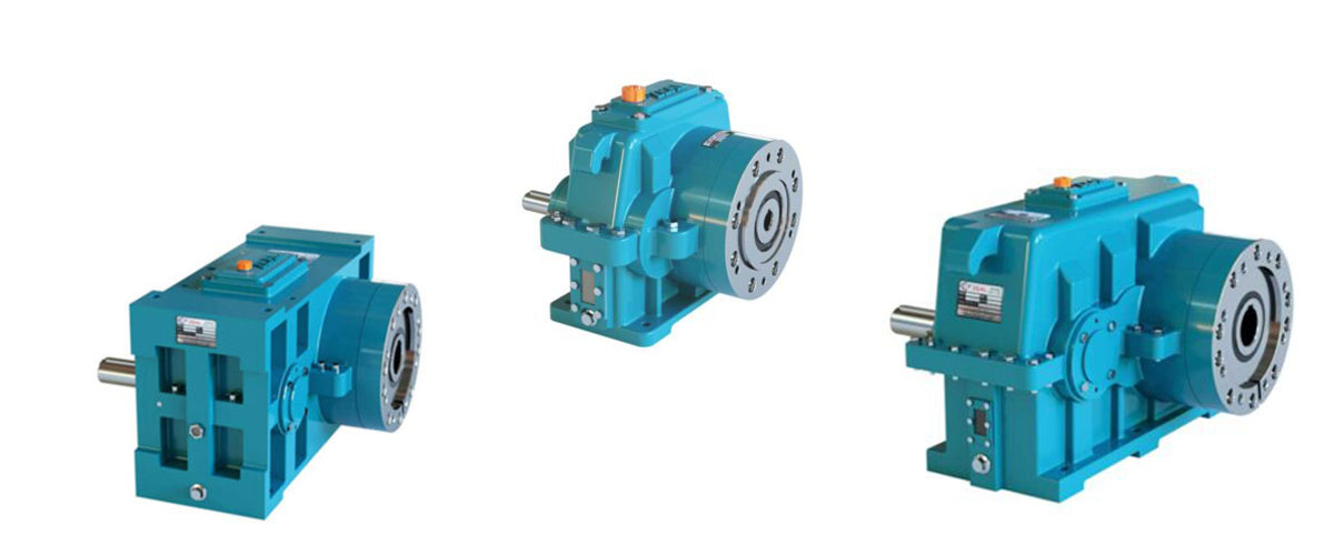
Quick Answer: An extruder gearbox for blown film plants is a heavy-duty speed reducer — almost always helical or helical-bevel with an integrated thrust bearing — that converts motor speed into the precise, continuous, high-torque, low-RPM screw rotation needed to maintain stable melt pressure and consistent film gauge.
Why Extruder Gearbox Reliability Is Critical for Blown Film Quality
The Thrust Load Problem Unique to Extrusion
Unlike a rubber mixer or a conveyor gearbox, which mostly handles radial or torsional load, an extruder screw pushes back against the gearbox with tremendous axial force as it compresses and forwards molten resin toward the die. This axial thrust — often tens of kilonewtons on a mid-size blown film line — is absorbed by a thrust bearing arrangement built directly into the gearbox output stage. If that thrust bearing is undersized, or if the gearbox was originally designed for a torsional-only application and adapted for extrusion duty, thrust bearing wear becomes the single most common and most expensive failure mode on the line.
Speed Stability Directly Controls Film Gauge
Blown film gauge thickness is a direct function of screw speed consistency, die geometry, and haul-off speed working in tight coordination. Even small speed fluctuations at the screw — caused by gear backlash, worn bearings, or an underdamped gear train — translate immediately into gauge bands visible in the finished roll. This is why extruder gearboxes for blown film applications are specified with tighter backlash and torsional stiffness tolerances than a general-purpose industrial gearbox rated for the same horsepower.
The Cost of Downtime on a Continuous Line
Blown film lines are typically run in continuous, multi-day or multi-week campaigns to minimize costly startup and purge cycles between resin or color changes. A gearbox failure mid-campaign does not just stop one machine — it forces a full purge, a cooldown, a repair or swap, and a full restart sequence that can waste hours of resin and labor before the line even returns to production speed. Because extruder gearboxes are frequently sized specifically to the screw diameter and motor combination on a given line, an unplanned failure often means an extended wait for a correctly matched replacement rather than a quick swap from stock.
There is a safety dimension as well. A gearbox nearing thrust bearing failure typically shows escalating noise, vibration, and heat for days before an outright failure, while continuing to run under load the entire time. Treating those early warning signs as an immediate shutdown-and-inspect trigger protects both the equipment and the operators working near a screw and die assembly carrying degraded, unpredictable torque transmission.
It is also worth recognizing that blown film plants rarely run a single extruder in isolation. Many lines run continuous three-shift schedules with minimal planned downtime built into the annual maintenance calendar, which means any gearbox weakness that would eventually surface as a scheduled repair on a single-shift operation instead surfaces as an unplanned, production-interrupting failure on a continuous blown film line. This operating reality is exactly why gearbox specification deserves more engineering rigor upfront than a general industrial application of similar horsepower would typically receive.
Types of Extruder Gearboxes Used in Blown Film Lines
Single-Reduction and Double-Reduction Helical Gearboxes
Helical gear reducers are the most common choice for small to mid-size blown film extruders because helical tooth engagement spreads load gradually across the tooth face, reducing noise and vibration while delivering the smooth torque transmission that speed stability depends on. Double-reduction helical units, using two gear stages in series, are typically specified on larger screw diameters where a single stage cannot achieve the required reduction ratio and torque output within a reasonable housing size.
Helical-Bevel Gearboxes
Where the motor axis needs to run perpendicular to the screw centerline — a common layout on many blown film extruders to keep the overall machine footprint compact — helical-bevel gearboxes combine a bevel gear stage for the right-angle direction change with helical stages for reduction. This configuration is extremely common on modern single-screw blown film extruders because it lets manufacturers keep the drive motor low and out of the way of operator access to the feed throat and hopper.
Planetary Gearboxes for Compact High-Torque Applications
Planetary gear stages appear on some blown film extruder designs, particularly larger-diameter screws or retrofits where floor space around the extruder barrel is limited but very high torque density is still required. Their compact torque-to-size ratio and generally lower backlash than a comparable helical stage make them attractive where gauge consistency and space constraints both matter, though they typically carry a higher unit cost than an equivalent helical-bevel design.
Integrated Thrust Bearing Housings
Regardless of gear architecture, the defining feature of a true extruder gearbox — as opposed to a general industrial gear reducer adapted for the job — is a purpose-built thrust bearing housing on the output stage, usually using tapered roller or spherical roller thrust bearings sized specifically for continuous axial screw loading. Gearboxes without an adequately rated thrust bearing package are the most common cause of premature failure when a general-purpose gearbox is mistakenly substituted for a purpose-built extruder unit to save on upfront cost.
Air-Cooled vs. Oil-Cooled Housings
Because blown film lines run continuously for extended campaigns, heat rejection is a bigger design consideration than on many intermittent-duty applications. Smaller gearboxes may rely on natural convection through a finned cast-iron housing, but mid-size and larger units commonly add a forced-air fan or a circulating oil cooler to hold oil temperature within a safe range across a multi-day run, particularly in plants located in hot climates or with limited floor ventilation around the extruder.
| Gearbox Type | Typical Configuration | Best Suited For | Key Consideration |
| Single-Reduction Helical | One gear stage | Small-diameter screws, lower ratios | Limited to lower reduction ratios |
| Double-Reduction Helical | Two gear stages in series | Mid-to-large screw diameters | Larger housing footprint |
| Helical-Bevel | Right-angle motor layout | Most modern single-screw extruders | Requires precise bevel alignment |
| Planetary | Compact epicyclic stage | Space-constrained, high-torque retrofits | Higher unit cost |
Key Technical Specifications for Blown Film Extruder Gearboxes
Specific Torque Rating (Nm per cm³)
The extrusion industry commonly rates extruder gearboxes using specific torque — output torque divided by the screw’s theoretical free volume — rather than a simple absolute torque figure, because this metric normalizes gearbox capability against the actual processing intensity the screw is designed for. Higher specific torque ratings, often expressed in Nm/cm³, indicate a gearbox capable of driving a more aggressive, higher-output screw design without becoming the bottleneck on line throughput. When comparing gearboxes across suppliers, always confirm which screw diameter and free-volume figure the specific torque number was calculated against, since manufacturers are not always consistent in how they present this figure.
Thrust Bearing Capacity
Axial thrust capacity is arguably the single most important specification unique to extruder gearboxes, since it is the parameter general industrial gear reducers most often get wrong when adapted for extrusion service. Thrust capacity must be verified against the maximum die-head back-pressure the line is expected to run, not just typical operating pressure, since pressure spikes during startup, screen-pack changes, or partial die blockages can exceed steady-state values significantly.
Output Speed Range and Turndown Ratio
Blown film lines frequently need to run across a range of screw speeds to accommodate different resin grades, film gauges, and output rate targets, so the gearbox’s rated speed range — and how efficiently it performs across that full turndown ratio, not just at its nominal design point — matters more here than on single-speed industrial applications.
Backlash and Torsional Stiffness
Because screw speed stability translates directly into film gauge consistency, extruder gearboxes for blown film service are typically specified with tighter backlash tolerances — often in the low single-digit arc-minute range — and higher torsional stiffness than an equivalent general-purpose industrial gearbox rated for similar power and speed.
Thermal Rating and Continuous Duty Classification
Given that blown film lines run 24/7 for extended campaigns, the gearbox’s continuous thermal rating must be verified against actual sustained torque and ambient plant temperature, not an intermittent-duty rating that assumes periodic cooling-off time the line will never actually get.
Motor and VFD Compatibility
Nearly all modern blown film extruders use a variable-frequency drive to control screw speed across a production range, so the gearbox’s rated speed range, thermal capacity, and bearing life calculations should be checked against the full VFD operating band, not just the motor’s nameplate speed, since running at the low end of a VFD’s range for extended periods can affect lubrication film formation in plain or rolling-element bearings differently than running near rated speed.
Efficiency and Energy Cost Over Continuous Duty
Because blown film lines run continuously for days or weeks at a time, even a small efficiency difference between gearbox designs compounds into a meaningful energy cost difference over a year of operation. A helical or helical-bevel gearbox running at 96–97% efficiency versus a less efficient alternative at 90% can represent a substantial difference in electricity cost on a large-diameter, high-output line, which is worth factoring into total cost of ownership alongside reliability and thrust bearing life when comparing supplier quotes.
Mounting Configuration and Center Height
Extruder gearboxes must align precisely with the barrel centerline and feed throat position, so mounting configuration — foot-mounted, flange-mounted, or a proprietary extruder-specific base — and output shaft center height need to match the extruder frame exactly, which is a critical consideration on any retrofit or gearbox replacement project.
| Parameter | Why It Matters for Blown Film Extrusion |
| Specific Torque (Nm/cm³) | Determines maximum screw output capability |
| Thrust Bearing Capacity (kN) | Absorbs axial load from die-head back-pressure |
| Output Speed Range | Must cover full resin/gauge processing window |
| Backlash | Directly affects film gauge consistency |
| Torsional Stiffness | Prevents speed oscillation under load changes |
| Thermal Rating (continuous) | Must hold up across multi-day production runs |
| Center Height / Mounting | Must align precisely with barrel and feed throat |
| Efficiency | Affects motor sizing and long-term energy cost |
Standards, Materials, and Lubrication Best Practices
Gear Rating Standards: AGMA, DIN 3990, and ISO 6336
Reputable extruder gearbox manufacturers calculate gear tooth strength and surface durability against recognized standards such as AGMA gear-rating methodology, DIN 3990, or ISO 6336, rather than quoting a torque figure without supporting calculation. When evaluating suppliers, ask specifically for the gear-rating calculation and the thrust bearing L10 life estimate at your actual operating conditions — a supplier that provides this documentation as standard practice is a materially different level of engineering partner than one offering only a catalog summary.
Gear and Shaft Material Selection
Extruder gearbox gear sets are typically manufactured from case-hardening alloy steels, carburized and hardened to a surface hardness in the 58–62 HRC range on the tooth flank while retaining a tougher core to resist fracture under the sustained torque loading typical of continuous extrusion duty. The output shaft, which carries both torsional load and the full axial thrust from the screw, deserves particular scrutiny at its bearing seats and keyway, since these are common stress-concentration points on high-duty-cycle extruder applications.
Lubricant Selection for Continuous-Duty Extrusion
Synthetic gear oils are the standard choice for continuous-duty blown film extruder gearboxes rather than mineral oils, because synthetic formulations resist viscosity breakdown at sustained elevated temperatures far better across the long, uninterrupted run times typical of blown film production, and they typically extend oil-change intervals two to four times longer than mineral oil under the same duty cycle. For food-contact film applications, verify whether an H1-rated food-grade lubricant is required by your customer’s compliance standards before specifying the gearbox’s lubrication package, since converting an in-service gearbox to food-grade oil later usually requires a full flush rather than a simple top-up.
Corrosion Protection and Sealing
Plants running high-humidity operations, frequent washdown cycles, or located in coastal or tropical climates benefit from corrosion-resistant housing coatings and upgraded shaft seals, since seal degradation and the resulting water ingress into the lubricant is a common, avoidable precursor to both bearing and gear-tooth damage on continuously run extruder gearboxes.
Monolayer vs. Multilayer Co-Extrusion: Gearbox Considerations
Single-Extruder Monolayer Lines
On a monolayer blown film line, gearbox selection is a relatively self-contained decision: one screw, one gearbox, one motor, sized against a single output target and resin type. The main variables to get right are torque, thrust capacity, and speed range matched to that one screw’s diameter and expected resin range.
Multilayer Co-Extrusion Lines Multiply the Precision Requirement
Multilayer coex lines run two, three, five, or more extruders simultaneously feeding a single die, each with its own gearbox, and the relative speed stability between them matters as much as the absolute accuracy of any single unit. If one extruder’s gearbox has looser backlash or worse speed stability than the others, that layer’s thickness will drift independently of the rest, showing up as a layer-distribution defect even when every other extruder on the line is performing perfectly. This is why coex lines often specify matched backlash and torsional stiffness tolerances across all extruder gearboxes on the line, rather than treating each one as an independent purchasing decision.
Standardizing Gearbox Specification Across a Coex Line
Plants running multilayer coex lines benefit from working with a single gearbox supplier across all extruder positions where possible, since this makes it easier to hold consistent backlash, thrust bearing rating, and lubrication specifications across every screw on the line — inconsistent sourcing across positions is a common, underappreciated contributor to intermittent layer-thickness variation that is otherwise difficult to diagnose.
Sizing the Smallest Layer Extruders Correctly
It is a common mistake to under-specify the gearboxes on smaller “skin layer” extruders in a coex stack, on the assumption that lower output naturally means lower engineering requirements. In practice, skin-layer extruders often need the same backlash and speed-stability tolerance as the core layer, since even a thin, low-output layer’s thickness variation is just as visible in the finished film as a variation in a thicker core layer.
How to Choose the Right Extruder Gearbox: A Step-by-Step Framework
Step 1: Confirm Screw Diameter, L/D Ratio, and Target Output Rate
Start from the extruder screw’s diameter, length-to-diameter (L/D) ratio, and the target output rate in kilograms per hour, since these three figures drive both the required torque and the specific torque density the gearbox must deliver — a higher L/D screw processing a more viscous resin at a given output rate demands meaningfully more torque than a shorter, lower-L/D screw at the same throughput.
Step 2: Calculate Required Torque and Thrust Load at Maximum Back-Pressure
Work with your screw and die supplier to establish maximum expected melt pressure at the die head, then convert that pressure figure into the axial thrust load the gearbox’s output bearing must absorb continuously, using the screw’s flight geometry — this figure, not the average operating pressure, is what the thrust bearing capacity must be checked against. Where possible, pull actual pressure transducer data from an existing similar line rather than relying solely on theoretical calculations, since real screen-pack condition, resin lot variation, and die restriction over a production campaign often push peak pressure higher than a clean theoretical model predicts.
Step 3: Match Reduction Ratio to Motor Speed and Screw RPM Range
Divide your motor’s rated speed by the screw RPM range your process requires, keeping in mind that blown film lines often need to run across a range of speeds for different resin grades and gauge targets, so the gearbox’s rated speed range needs headroom rather than being sized to a single nominal operating point.
Step 4: Verify Thermal Capacity Against Continuous 24/7 Duty
Confirm the gearbox’s continuous thermal rating, not an intermittent-duty figure, covers your actual sustained torque output at your plant’s real ambient temperature, and specify oil cooling or forced-air cooling up front if the calculated heat load is close to the housing’s natural dissipation limit, since blown film lines rarely get the cooling-off periods an intermittent-duty rating assumes.
Step 5: Confirm Mounting, Center Height, and Coupling Compatibility
Check output shaft center height, mounting footprint, and coupling type against your existing or planned extruder frame exactly, particularly on a replacement or retrofit project where a slight mismatch can mean re-machining the extruder base or ordering a custom adapter plate.
Step 6: Specify Backlash and Torsional Stiffness Tolerances Explicitly
Do not assume a standard industrial gearbox’s default backlash specification is tight enough for blown film gauge control — request the manufacturer’s backlash figure explicitly and compare it against your line’s gauge tolerance requirements, especially on thin-gauge or high-clarity film applications where speed stability matters most.
Step 7: Request Full Documentation Before Purchase
Ask for gear-rating calculations against AGMA, DIN, or ISO 6336 standards, thrust bearing L10 life estimates at your actual operating load, and thermal capacity data referenced to your plant’s ambient temperature — this documentation, not a catalog torque number alone, is what actually tells you whether a gearbox will reach its expected service life on your specific line.
Maintenance, Troubleshooting, and Real-World Failure Scenarios
Routine Maintenance Practices
- Scheduled oil analysis — Sample gearbox oil every three to six months to catch water contamination, wear metal particles, or additive breakdown before they progress to gear or bearing damage, particularly important given the extended continuous run times typical of blown film production.
- Vibration monitoring — Establish a baseline vibration signature at commissioning and track drift over time, since a developing thrust bearing fault typically shows up in the vibration spectrum well before it becomes audible or causes a process disturbance.
- Thermal imaging during full-speed operation — Scan the gearbox housing and thrust bearing area during sustained full-speed runs to catch developing hotspots before they progress to lubricant breakdown or bearing failure.
- Alignment verification after coupling work — Re-check shaft alignment any time the motor, coupling, or gearbox is disturbed for any reason, since misalignment accelerates both gear wear and thrust bearing degradation on continuously loaded extruder drives.
- Seal and breather inspection at scheduled shutdowns — Replace shaft seals proactively during planned maintenance windows rather than waiting for visible leakage, since blown film plants rarely get an unplanned opportunity to address a slow leak before it becomes contamination.
- Spare parts and lead-time planning — Because extruder gearboxes are frequently sized specifically to a given screw and motor combination, replacement lead times can run from several weeks to a few months. Keeping a spare gearbox or, at minimum, spare thrust bearings and seals on site for critical lines substantially reduces the production risk of an unplanned failure, and is almost always cheaper than the lost output of an extended unplanned outage.
Common Failure Patterns and Root Causes
Thrust bearing failure is the most frequent and most expensive extruder gearbox failure mode in blown film applications, almost always traced back to a thrust bearing undersized for actual maximum back-pressure, or a general-purpose gearbox substituted for a purpose-built extruder unit. Gear-tooth pitting and micro-pitting typically results from insufficient specific torque rating relative to actual screw output, contaminated or degraded lubricant, or a gearbox running near its continuous torque limit for extended periods rather than with reasonable margin. Speed instability and gauge drift most often points to developing backlash from gear or bearing wear, rather than a die-head or haul-off issue, which is why gearbox condition should be one of the first things checked when gauge variation appears without an obvious process change.
A Real-World Example
A mid-size blown film converter experienced recurring gearbox failures on a line running high-output HDPE film, with the gearbox needing thrust bearing replacement roughly every fourteen months against an expected multi-year service life. Investigation traced the issue to two compounding factors: the original gearbox had been specified using average operating pressure rather than the higher back-pressure the line actually reached during screen-pack changes, and the plant had been using a mineral-based gear oil with change intervals too long for the sustained high-temperature, continuous-duty operation. Re-specifying the replacement gearbox with a thrust bearing rated for peak back-pressure, combined with switching to a synthetic gear oil on a shorter, more disciplined change interval, extended service life beyond four years — a clear illustration of how closely gearbox reliability tracks real operating conditions rather than average or nominal figures.
Extruder Gearbox Solutions Built for Blown Film Lines
If your plant is experiencing recurring extruder gearbox failures, planning a new blown film line, or retrofitting an existing extruder with higher-output capability, the fastest path to a reliable outcome is working with a supplier who engineers to your actual screw, resin, and back-pressure data rather than selling from a generic catalog page. The right partner reviews your screw diameter, target output rate, and maximum expected die-head pressure, applies the correct thrust bearing rating and specific torque calculation for your application, and confirms thermal capacity against your real continuous-duty schedule before a gearbox is ever built.
Look for concrete signals of that kind of engineering partner: gear-rating calculations and thrust bearing L10 life estimates provided as standard documentation rather than on request only, in-house capability to support OEM-compatible replacement units for existing extruder frames, and manufacturing quality control that includes dimensional, hardness, and load testing before dispatch. It also helps to work with a supplier who can support reverse-engineered replacements from an existing gearbox’s drawing or sample, since many blown film lines run older extruder frames where the original gearbox model is long out of production.
Plants that have standardized on correctly specified, purpose-built extruder gearboxes consistently report longer intervals between overhauls and fewer unplanned mid-campaign stoppages compared to relying on adapted general-purpose gear reducers. If you’re specifying a new extruder gearbox or replacing a recurring problem unit, our engineering team can review your screw, resin, and pressure data and recommend a correctly rated gearbox — including OEM-compatible replacements for existing blown film lines.
Frequently Asked Questions
Q1. What makes an extruder gearbox different from a standard industrial gearbox?
An extruder gearbox is built with a dedicated thrust bearing housing sized specifically to absorb the continuous axial force a screw generates against die-head back-pressure, along with tighter backlash and torsional stiffness tolerances than a standard industrial gear reducer, both of which are essential for maintaining stable screw speed and consistent film gauge.
Q2. How long should an extruder gearbox last on a blown film line?
A correctly specified and well-maintained extruder gearbox for blown film service should typically run five to ten years or longer between major overhauls. Units failing within one to two years almost always point to an undersized thrust bearing, insufficient specific torque rating, or an inadequate lubrication and maintenance schedule rather than normal wear.
Q3. What thrust bearing rating do I need for my blown film extruder?
Thrust bearing rating must be sized against the maximum die-head back-pressure your line will actually reach, including pressure spikes during startup or screen-pack changes, not just typical steady-state operating pressure — always confirm this maximum figure with your screw and die supplier before finalizing gearbox specification.
Q4. Can I use a general-purpose helical gearbox instead of a purpose-built extruder gearbox?
This is generally not recommended for continuous blown film production, because general-purpose gearboxes are rarely rated for the sustained axial thrust loading extrusion generates, and substituting one to save upfront cost is one of the most common causes of premature thrust bearing failure on extrusion lines.
Q5. Why is my film gauge inconsistent even though my die and haul-off settings haven’t changed?
Inconsistent gauge without a process change is frequently traced back to developing gearbox backlash or bearing wear causing small screw speed fluctuations, so checking gearbox vibration signature and backlash should be an early diagnostic step before adjusting die or haul-off settings further.
Q6. What lubricant is best for a continuous-duty blown film extruder gearbox?
Synthetic gear oil is generally the better choice for continuous-duty blown film extrusion because it resists viscosity breakdown at sustained high operating temperatures and extends oil-change intervals significantly compared to mineral oil, often offsetting its higher upfront cost through reduced maintenance labor alone.
Q7. How often should extruder gearbox oil be sampled or changed?
Oil analysis every three to six months is a reasonable baseline for continuous-duty blown film extruder gearboxes, though the actual change interval should be based on lab analysis results — additive depletion, contamination, and viscosity drift — rather than a fixed calendar schedule alone.
Q8. Can an existing extruder gearbox be reconditioned instead of replaced?
In many cases, yes — gear sets, thrust bearings, and seals can often be reconditioned within the original housing if the housing itself and gear teeth are not structurally damaged, which is typically more cost-effective and faster than a full replacement, provided a qualified shop inspects the unit first.
Q9. How do I size a replacement gearbox for an older extruder line where the original model is discontinued?
Provide the extruder frame’s mounting dimensions, output shaft center height, screw diameter, and target output rate to a supplier capable of reverse-engineering from a drawing or physical sample, since matching these physical and performance parameters is usually more reliable than trying to match the original manufacturer’s model number alone.
Conclusion
An extruder gearbox for blown film plants carries far more responsibility than its position at the back of the machine suggests. It absorbs the continuous axial thrust of the screw pushing against die-head pressure, holds the precise, stable speed that film gauge consistency depends on, and determines — more than almost any other single drive-train component — how many unplanned stoppages a continuous production campaign experiences. Getting the specification right starts with real screw, resin, and back-pressure data rather than catalog assumptions, sizing the thrust bearing against peak rather than average pressure, and verifying continuous thermal capacity against your plant’s actual 24/7 duty cycle.
Across single-reduction helical, double-reduction helical, helical-bevel, and planetary designs, the right choice always comes back to matching the gearbox’s engineering to your specific screw diameter, output target, and back-pressure profile. Combined with disciplined maintenance — oil analysis, vibration monitoring, alignment checks, and proactive seal replacement — a correctly specified extruder gearbox can comfortably outlast a poorly matched one by several years, saving far more in avoided downtime and scrapped production than it ever cost upfront.
For plants running multilayer co-extrusion, the same principles apply across every extruder position on the line, with the added requirement of matched backlash and speed-stability tolerances so that no single layer’s gearbox becomes the weak link behind a hard-to-diagnose layer-thickness defect. None of this requires guesswork — real screw, resin, and pressure data, an honestly rated thrust bearing, and documentation you can actually verify are what turn extruder gearbox selection from a catalog gamble into a straightforward engineering decision.
If your blown film line is experiencing recurring gearbox issues or you’re specifying a new extruder, get in touch with our engineering team for a free screw and pressure-data review and gearbox recommendation tailored to your line.
