
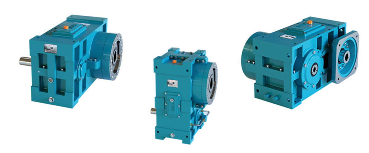
Quick Answer: Correct gearbox alignment keeps the extruder screw shaft and gearbox output shaft on the same rotational centerline, within a few hundredths of a millimeter. Getting this right — using dial indicator or laser methods, checked at every service interval and after any foundation or thermal change — is one of the single most effective ways to cut vibration, extend bearing life, and avoid unplanned extruder downtime.
Why Alignment Matters More on Extrusion Machines
Extrusion machines run differently than most rotating equipment. A plastic or rubber extruder gearbox doesn’t just spin a shaft — it drives a screw under continuous, heavy, and often uneven torque, pushing material against die resistance for weeks or months without a real stop. That combination of constant load, elevated ambient heat from the barrel, and long uninterrupted run times means even small alignment errors compound faster than they would on a simple pump or fan drive.
Misalignment between the gearbox output shaft and the extruder screw shaft is one of the most common — and most preventable — causes of premature bearing wear, coupling failure, and seal leakage on extrusion lines. It rarely announces itself immediately. Instead, it shows up gradually: a slight vibration that maintenance teams get used to, a coupling that runs a little warmer than it should, a bearing that wears unevenly on one side. By the time the symptoms are obvious, the damage to the bearing race and coupling has often already been done.
The upside is that alignment is one of the most controllable variables in extruder gearbox reliability. It doesn’t require redesigning the machine or buying new equipment — it requires the right method, the right tolerance target, and the discipline to check it on a schedule rather than only after something breaks. Correcting misalignment can reduce vibration substantially and extend bearing life several times over compared to a poorly aligned drive, which makes it one of the highest-return maintenance activities available to any extrusion plant.
This guide walks through what misalignment actually looks like inside an extruder gearbox, the tolerance standards to work toward, and the specific practices that keep alignment within spec between major service intervals.
Understanding Misalignment: Types, Tolerances, and Root Causes
Before correcting misalignment, it helps to understand exactly what is being measured and why the tolerance is so tight.
Parallel (Offset) vs. Angular Misalignment
Shaft misalignment comes in two basic forms, and most real-world cases are a combination of both. Parallel (or offset) misalignment happens when the two shaft centerlines are parallel to each other but not on the same line — like two train tracks running side by side instead of merging into one. Angular misalignment happens when the shaft centerlines meet at an angle rather than running parallel, so the gap between them widens on one side of the coupling. A gearbox can be perfectly positioned in one plane and still be out of tolerance in the other, which is why both are checked independently during any proper alignment procedure.
Why Tolerances Get Tighter at Higher Speeds
Alignment tolerance is not a single fixed number — it scales with running speed, because misalignment forces grow with the square of shaft speed, so faster-running equipment needs proportionally tighter alignment than slower machines. For equipment running around 1,500 to 1,800 RPM, a widely used rule of thumb keeps offset within about 0.05 mm and angularity within roughly 0.05 mm per 100 mm of coupling diameter, with progressively tighter limits as speed increases. Most extruder gearbox input shafts run near standard motor speed, while the output shaft — coupled directly to the screw — typically runs much slower, so both the high-speed input coupling and the low-speed output coupling need to be checked against their own appropriate tolerance.
The Three Root Causes Behind Most Misalignment
- Installation error: The gearbox was never precisely aligned when first installed, or shims were removed or disturbed during a later repair.
- Soft foot: One or more mounting feet don’t sit flush on the baseplate, so tightening the bolts twists the gearbox housing slightly out of true — a condition that must be corrected before alignment, not after.
- Thermal growth and foundation movement: As the gearbox and extruder barrel heat up during operation, metal expansion shifts shaft centerlines from their cold, as-installed position. A machine aligned cold can be measurably out of alignment once it reaches normal running temperature.
What Misalignment Actually Damages
| Component Affected | How Misalignment Damages It |
| Bearings | Uneven load distribution across rolling elements causes localized pitting, spalling, and premature race wear |
| Coupling | Elevated cyclic stress accelerates elastomer or gear-tooth coupling wear and can cause sudden coupling failure |
| Seals | Shaft whip and vibration wear grooves into seal lips, leading to oil leakage and contamination ingress |
| Gear teeth | Indirect load shifts inside the gearbox can concentrate contact stress unevenly across the gear face |
7 Best Practices for Aligning Extruder Gearboxes
Correct Soft Foot Before Every Alignment
Never attempt to align a gearbox with an uncorrected soft foot condition. Loosen each mounting bolt individually and measure the gap at each foot with a feeler gauge or dial indicator; shim any foot that doesn’t sit flush before proceeding. Aligning on top of a soft foot condition produces numbers that look correct on the gauge but shift as soon as the bolts are torqued down.
Choose the Right Measurement Method for the Job
Dial indicator methods — rim and face or reverse dial — remain accurate when performed carefully, but they are slower and more sensitive to bracket sag errors. Laser alignment systems measure offset and angularity in both planes directly and display live guided corrections as the machine is shimmed and shifted, cutting a typical two-hour dial-based alignment down to well under an hour with more consistent, repeatable results. For extruder gearboxes handling heavy thrust loads, the speed and repeatability of laser alignment make it the preferred method wherever the equipment is available.
Align to the Machine’s Actual Operating Temperature, Not Just Cold Position
Where thermal growth data is available for the gearbox and extruder, factor it into the alignment target so the shafts land on-center once the machine reaches normal running temperature — not just when it’s aligned cold at startup. If thermal growth figures aren’t available from the OEM, at minimum re-check alignment readings after the line has run long enough to reach steady-state operating temperature.
Set Tolerance by Actual RPM, Not a Generic Standard
Don’t apply a single blanket tolerance across every gearbox in the plant. Set the alignment tolerance based on the actual shaft speed of each coupling — input and output shafts on the same gearbox often run at very different speeds and therefore need different tolerance targets. Most laser alignment tools can generate a tolerance table automatically once the RPM and coupling dimensions are entered.
Re-Torque and Re-Verify After Final Bolt-Down
Alignment numbers can shift slightly as mounting bolts are torqued to final spec, especially if any shims were adjusted during the process. Always take a final verification reading after all bolts are fully torqued — not just after the last shim adjustment — to confirm the as-left condition matches what will actually run in production.
Recheck Alignment on a Fixed Schedule and After Any Disturbance
Build alignment verification into the planned maintenance calendar rather than treating it as a one-time installation task. Recheck alignment after any event that could disturb it: a coupling replacement, a foundation repair, a major process upset, or simply as part of a scheduled quarterly or annual inspection. A machine that was correctly aligned six months ago and is now out of tolerance is telling you something is moving underneath it — a foundation, a pipe strain, or a soft foot condition and that root cause needs investigating, not just re-shimming.
Log As-Found and As-Left Readings Every Time
Record the misalignment values measured before correction (as-found) and after correction (as-left) for every alignment job, along with the date and RPM used to set tolerance. Over time, this log reveals whether a particular gearbox is drifting out of alignment faster than expected, which is often the earliest indicator of a developing foundation, coupling, or mounting problem.
How Zeal Gears Supports Precision Gearbox Installation
Correct alignment starts with a gearbox that’s engineered to make precise installation achievable in the first place. Zeal Gears Pvt. Ltd., a helical gearbox manufacturer based in Ahmedabad, Gujarat, designs its Extruder Helical Gearbox range with an inbuilt thrust block and mounting configurations — including universal mounting, vertical mounting, and input-flange options — engineered to give installation teams a stable, repeatable reference for accurate shaft alignment from day one.
Because the gearbox housing is precision-machined and cast in graded iron for dimensional stability, and gears are manufactured from high-graded alloy steel to the tight tolerances required for smooth helical gear engagement, the mounting surfaces hold their position reliably even under continuous extrusion duty — reducing the risk of the gearbox itself introducing misalignment over time. Zeal Gears’ technicians also guide customers through gearbox selection to match speed, torque, and thrust requirements to the specific extruder application, which reduces the risk of a mismatched or oversized unit that’s harder to align and maintain correctly. Learn more about the company’s full gear box services, including selection support, preventive maintenance guidance, and repair of existing installations.
FAQs on Extruder Gearbox Alignment
Q1. What is the acceptable alignment tolerance for an extruder gearbox?
Tolerance depends on shaft speed rather than a single fixed number. As a general guide, machines running near 1,500 to 1,800 RPM should be aligned to within roughly 0.05 mm offset and about 0.05 mm per 100 mm of coupling diameter for angularity, with tighter limits required as speed increases. Always confirm the specific tolerance recommended by your gearbox and coupling manufacturer.
Q2. How often should extruder gearbox alignment be checked?
At minimum, alignment should be verified during every planned maintenance shutdown and after any event that could disturb it, such as a coupling replacement, foundation repair, or major process upset. Many plants also schedule a dedicated quarterly or annual alignment check as part of their preventive maintenance program, even if no issue has been reported.
Q3. What’s the difference between laser and dial indicator alignment methods?
Both methods can achieve accurate results, but laser alignment systems measure offset and angularity directly in both planes and display live guided corrections, typically completing an alignment job in well under an hour. Dial indicator methods such as rim and face or reverse dial remain accurate when performed carefully, but they take longer and are more sensitive to setup errors like bracket sag.
Q4. Can misalignment cause a gearbox to fail even if the oil level and lubrication are fine?
Yes. Misalignment concentrates load unevenly on the bearing rollers and coupling regardless of lubrication quality, causing localized pitting, spalling, and coupling wear that good lubrication alone cannot prevent. Proper lubrication and correct alignment address two different failure mechanisms, and both need to be maintained together for reliable gearbox operation.
Q5. Why does my gearbox go out of alignment even though nothing was touched?
The most common causes are thermal growth as the machine reaches operating temperature, gradual foundation settling, or a soft foot condition that wasn’t fully corrected during the original installation. If a gearbox repeatedly drifts out of tolerance between checks, it usually points to a root cause like foundation movement rather than a one-time alignment error.
Q6. Does soft foot need to be fixed before or after alignment?
Soft foot must always be corrected before alignment begins. If a mounting foot doesn’t sit flush and the bolts are tightened anyway, the housing twists slightly out of true, which produces alignment readings that appear correct on the gauge but shift as soon as the machine is put into service.
Key Takeaways
Precision gearbox alignment is one of the highest-return maintenance practices available for extrusion machines, because misalignment forces increase sharply with shaft speed and compound quickly under the continuous, heavy-torque duty cycle typical of plastic and rubber extrusion. Correcting soft foot first, choosing laser alignment where possible, setting tolerance by actual RPM, and rechecking alignment on a fixed schedule together prevent the majority of coupling failures, seal leaks, and premature bearing wear traced back to misalignment. Just as important is starting with a gearbox built for dimensional stability under continuous duty — a precision-machined mounting base holds its alignment far longer than a lower-quality casting under the same load.
If you’re installing a new extruder gearbox or want guidance on selecting a unit built for reliable long-term alignment, contact Zeal Gears for gearbox selection support or a free quote.
