
Introduction
Open up almost any twin screw extruder — whether it’s compounding masterbatch, producing PVC pipe, or texturising a snack food — and behind the barrel you’ll find a component doing far more mechanical work than most process engineers give it credit for. A twin screw extruder gearbox doesn’t just reduce motor speed and multiply torque the way a single-screw gearbox does; it also has to split that torque between two output shafts and hold them in a fixed, precise angular relationship to each other for the entire life of the machine, at loads and speeds that vary constantly with the material being processed. This guide explains exactly what a twin screw extruder gearbox is, what’s inside it, how the two main design families — co-rotating and counter-rotating — differ, which industries rely on each, and what to check when you’re specifying or buying one. The distinction matters more than it might first appear, because a twin-screw gearbox sitting on the wrong side of the co-rotating/counter-rotating or parallel/conical decision won’t just underperform — it typically can’t process the intended material at all, or does so at a quality and consistency well below what the application needs. Unlike a single-screw gearbox, where an undersized unit might simply run hotter or wear faster, a twin-screw gearbox mismatched to its process is often a fundamental design incompatibility rather than a sizing margin problem, which is why understanding these distinctions before specification matters more here than in almost any other extrusion drive-train decision.
What Is a Twin Screw Extruder Gearbox?
A twin screw extruder gearbox is a specialised speed-reduction and torque-transmission unit that drives and synchronizes two intermeshing extruder screws from a single motor. It takes the motor’s relatively high input speed — typically around 1500 rpm — and converts it into the low, precisely controlled output speed the screws need, while multiplying torque proportionally and splitting that torque evenly between two output shafts that must rotate at an identical, fixed angular relationship to one another.
Why Twin Screw Extruders Need a Different Gearbox Than Single Screw
A single-screw extruder gearbox only has to solve one problem: deliver enough torque to one output shaft at the right speed, and absorb the axial thrust that shaft generates. A twin-screw gearbox has to solve that same problem twice, simultaneously, on two shafts that are mechanically linked to each other through the intermeshing screw flights in the barrel. If the two output shafts drift out of their fixed timing relationship by even a fraction of a degree, the screw flights can make physical contact inside the barrel — something that never happens on a single-screw machine and that can destroy both screws and the gearbox internals in seconds. This synchronization requirement, more than raw torque capacity, is what makes twin-screw gearbox design fundamentally different from single-screw gearbox design.
Inside a Twin Screw Extruder Gearbox: Core Components
Most twin screw extruder gearboxes are built from three functional sections housed together, plus the lubrication and cooling system that keeps them running within safe temperature limits.
The Reduction Section
The reduction section is closest to the motor and performs the primary speed reduction and torque multiplication, using one or more stages of helical gearing depending on the overall ratio required. This section determines the base torque and speed the rest of the gearbox has to work with, and its gear ratio is typically fixed at the point of manufacture or selected from a limited range of standard ratios to match different process requirements.
The Distribution Section
Downstream of the reduction section, the distribution section splits the single reduced-speed input into two output lines feeding the two screw shafts. On a parallel twin-screw gearbox this is usually a set of gears holding the two output shafts at a fixed center distance; on a conical design, a long shaft and a short shaft are driven at a matched angle through a precise drive ratio, commonly 1:1, so both screws rotate at identical speed and fixed relative timing. Distribution-section gear tolerance and backlash control are what actually keeps the two screws synchronized under load.
Thrust Bearing Housing and Pressure Flange
Because each screw independently generates axial back-pressure as it works against the die restriction, a twin-screw gearbox needs a thrust bearing housing and pressure flange on each output line, not just one shared bearing arrangement. This is typically combined with the distribution section as a single mechanical assembly, since the thrust load path and the synchronization requirement both converge at the same point in the gear train.
Lubrication and Cooling System
Twin-screw gearboxes generate more internal heat than an equivalent single-screw unit, both because they are transmitting torque through more gear meshes and because many twin-screw applications run continuously at high duty. Most units beyond a modest power rating use forced lubrication — a motor-driven oil pump feeding filtered, cooled oil to the gear meshes and bearings — rather than relying on splash lubrication alone, and this system needs to be sized to the gearbox’s actual continuous heat load, not just its rated torque.
Coupling and Output Shaft Design
The output shafts that connect the gearbox to the screw shafts typically use a splined or keyed coupling toothing designed to transmit torque without backlash while still allowing the screws to be withdrawn from the barrel for cleaning, inspection, or screw-element reconfiguration — a routine maintenance need on modular twin-screw compounding lines in particular. On conical gearboxes, the output shafts are additionally set at the same conical angle as the screws themselves, which adds a geometric constraint to the coupling design that parallel-shaft gearboxes don’t have to account for. Getting this coupling interface wrong, even when the gear train itself is correctly sized, can introduce exactly the kind of angular play that undermines the shaft synchronization the rest of the gearbox is designed to protect.
Co-Rotating vs Counter-Rotating Twin Screw Gearboxes
The single most important design decision in a twin-screw gearbox is whether the two output shafts turn in the same direction (co-rotating) or opposite directions (counter-rotating), and this choice is driven entirely by what the extruder needs to process.
It’s worth noting that this decision is generally made once, at the design stage of the extruder line as a whole, rather than something a gearbox can be reconfigured to do later — the barrel geometry, screw element design, and gearbox distribution gearing are all built around one rotation direction or the other. This is different from, say, a mounting orientation, which a supplier might offer as a configurable option on an otherwise standard gearbox. A plant evaluating a used or reconditioned twin-screw gearbox for a new application should treat the co-rotating/counter-rotating question as a hard compatibility check, not a specification to be adjusted after purchase.
Co-rotating twin screws, where both shafts turn the same way, create intense self-wiping action between the two screws and generate high shear — exactly what’s needed for thorough dispersive mixing of fillers, pigments, and additives into a polymer melt. This makes co-rotating gearboxes the standard choice for compounding, masterbatch production, and other applications where mixing quality matters more than gentle, low-shear processing.
Counter-rotating twin screws, where the shafts turn in opposite directions, transport material mechanically through the intermeshing flights rather than relying on viscous shear, which allows the screws to run only partially filled for much of their length. This significantly reduces shear-induced heating, which is exactly the behaviour needed when processing thermally sensitive materials or powder feedstock, and is why counter-rotating gearboxes dominate rigid PVC pipe and profile extrusion.
| Factor | Co-Rotating Gearbox | Counter-Rotating Gearbox |
| Shaft Rotation | Both shafts turn the same direction | Shafts turn in opposite directions |
| Primary Strength | High shear, thorough dispersive mixing | Gentle, mechanical conveying with low shear heat |
| Common Materials | Filled and pigmented polymer melts | Rigid PVC powder, heat-sensitive compounds |
| Typical Applications | Compounding, masterbatch, food extrusion | PVC pipe and profile extrusion |
| Synchronization Demand | High, continuous intermesh under shear load | High, precise timing against back-pressure |
Parallel vs Conical Twin Screw Gearbox Layouts
Independent of the co-rotating or counter-rotating decision, a twin-screw gearbox is also built in one of two physical shaft layouts.
Parallel Twin Screw Gearboxes
Parallel gearboxes hold the two output shafts at a fixed, equal center distance along their full length, matching cylindrical screws of constant diameter. This layout generally supports higher output rates and larger screw diameters, and is the standard configuration for large-scale compounding and masterbatch lines.
Conical Twin Screw Gearboxes
Conical gearboxes drive a long shaft and a short shaft at a matched angle, powering tapered screws that narrow toward the discharge end. The deeper feed section this geometry creates is well suited to compacting powder feedstock, which is one reason conical twin-screw gearboxes are common on smaller and mid-range rigid PVC pipe and profile lines processing dry-blend compound.
Industries and Applications That Rely on Twin Screw Gearboxes
Twin-screw extrusion technology, and the gearboxes that drive it, show up across a wider range of industries than most people outside plastics processing realise.
- Plastic compounding and masterbatch: Co-rotating parallel twin-screw gearboxes drive the extruders that disperse pigments, fillers, and functional additives into polymer carriers, where thorough, uniform mixing is the primary process objective.
- Rigid PVC pipe and profile extrusion: Counter-rotating parallel or conical twin-screw gearboxes drive the extruders that process PVC dry-blend powder into pipe, window profile, and siding, where gentle, low-shear conveying protects the thermally sensitive material.
- Wood-plastic composite (WPC) extrusion: Twin-screw gearboxes drive the extruders that process wood-fibre-filled polymer compounds into decking, fencing, and profile products, a duty that combines high torque demand with significant material abrasiveness.
- Food and feed extrusion: Twin-screw gearboxes drive extruders that texturise, cook, and shape snack foods, breakfast cereals, pet food, and animal feed, where consistent shear and residence time directly determine finished product texture.
- Rubber processing: Twin-screw extruders devolatilize and shape rubber compounds in applications ranging from tyre component production to industrial rubber profile extrusion.
- Chemical and pharmaceutical processing: Twin-screw extrusion is increasingly used for continuous chemical reaction and pharmaceutical hot-melt extrusion, where precise, repeatable torque and residence time control matter as much as they do in polymer processing.
Across all of these industries, the underlying gearbox engineering challenge stays the same — deliver enough torque to two synchronized shafts without letting them drift out of timing — even though the specific torque, speed, and thrust figures the gearbox needs to hit vary enormously between, say, a low-viscosity food dough and a filled, abrasive PVC compound. This is why twin-screw gearbox manufacturers typically offer a range of ratios, center distances, and torque ratings within each shaft-layout family rather than a single fixed design, and why application-specific sizing matters as much on a twin-screw gearbox as the co-rotating/counter-rotating and parallel/conical decisions do.
How Torque Is Split and Synchronized Across Two Screws
Understanding how a twin-screw gearbox actually divides and controls torque helps explain why these units are specified so differently from single-screw gearboxes.
The reduction section delivers a single torque and speed value into the distribution section, which then splits that torque across the two output shafts through meshing gears in fixed proportion — on most designs, essentially an even split, though the two shafts may see slightly different net loading depending on how the screws’ resistance differs during processing. What matters more than the raw torque split is that the distribution gearing holds both shafts at an identical, fixed angular position under all load conditions, since the intermeshing screw flights depend on that timing relationship never drifting, even under the varying resistance a changing material feed rate or viscosity creates.
Gearbox engineers describe a twin-screw unit’s capability through torque density — the torque delivered per shaft relative to the cube of the center distance between the two shafts — rather than a simple output torque figure in isolation. At a given center distance, the ratio of outer to inner screw diameter is set as high as practically possible, since this expands the process-relevant volume the screws can work with for a given mechanical footprint. Two gearboxes rated at similar output torque can behave very differently on the same application depending on this torque-density design, which is why comparing catalogue torque figures alone rarely tells the full story.
Choosing the Right Twin Screw Gearbox: Key Specifications to Check
Whether you’re compounding masterbatch, extruding PVC pipe, or processing food, the same core specifications determine whether a twin-screw gearbox will perform reliably on your application. Because the co-rotating/counter-rotating decision and the parallel/conical layout decision are largely fixed by process requirements rather than preference, the specifications below are what actually differentiate two gearboxes competing for the same application once those two decisions are already made.
- Co-rotating or counter-rotating: This is decided by your process, not your preference — high-shear mixing applications need co-rotating; thermally sensitive or powder-fed applications generally need counter-rotating.
- Parallel or conical shaft layout: Larger, higher-output lines typically favour parallel; smaller lines processing powder feedstock often favour the deeper feed section a conical layout provides.
- Output torque and torque density: Confirm both the absolute output torque rating per shaft and the torque-density figure relative to center distance, since two gearboxes with similar headline torque can differ meaningfully in real capability.
- Center distance and screw diameter compatibility: The gearbox’s center distance must match your intended screw diameter and Do/Di ratio — this is not a figure that can be adjusted after the fact.
- Thrust bearing rating on both shafts: Each output shaft needs independently verified thrust bearing capacity against the axial back-pressure your die and screw geometry generate.
- Synchronization tolerance and backlash: Ask for the gearbox’s rated backlash and synchronization accuracy specifically — this rarely appears on a basic torque-and-power datasheet but directly determines service life.
- Lubrication and cooling provision: Confirm whether splash lubrication is adequate for your duty cycle or whether continuous, high-torque operation requires a forced system with an external cooler.
- Housing material and corrosion protection: Applications processing abrasive fillers or corrosive trace by-products need wear- and corrosion-resistant internal linings and coatings, not a standard general-purpose housing.
Zeal Gears Twin Screw Extruder Gearboxes
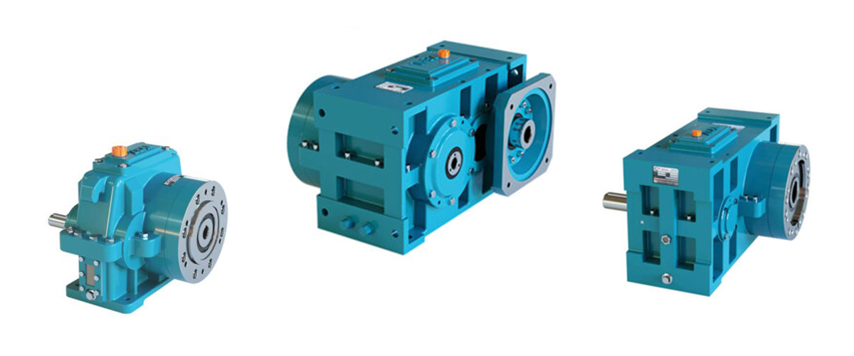
Zeal Gears manufactures twin screw extruder gearboxes for plastic, rubber, and food processing applications, engineered to synchronize two intermeshing shafts precisely under continuous load. Our twin screw extruder gearbox range includes a twin-shaft configuration available across an 18.5 mm to 76 mm center-distance range, along with a conical SZ-series design driving matched long and short shafts at a 1:1 ratio, both built with robust housing construction and efficient cooling provision for high-load, continuous-duty operation.
Every unit is customised to the customer’s specific torque, output, and synchronization requirement rather than sold off a fixed catalogue size alone, and is backed by Zeal Gears’ in-house repair and rebuilding department for genuine spare-part support across the gearbox’s working life. As an ISO 9001 certified manufacturer established in 1996, with more than 15,000 installations spanning plastic pipe, blown film, blow moulding, plastic granule, food, and rubber applications, Zeal Gears runs every gearbox through a no-load test before dispatch.
Maintenance and Common Failure Points
Twin-screw gearboxes fail differently from single-screw units, and knowing where to look catches most problems before they become costly.
- Synchronization drift: Backlash or timing drift between the two output shafts is the failure mode unique to twin-screw gearboxes, and should be checked as part of routine inspection, not only after abnormal noise or vibration appears.
- Independent thrust bearing wear: Because each shaft carries its own axial load, a bearing inspection that only checks one side can miss developing fatigue on the other — both shafts need independent inspection.
- Lubrication breakdown under continuous duty: High-torque-density twin-screw gearboxes generate more heat per unit size than many single-screw units, so oil condition should be monitored on a running-hours basis, particularly on continuous multi-shift operations.
- Distribution-gear wear from cyclic loading: Applications with frequent material or recipe changes put the distribution gearing through more load cycling than steady, single-product operation, which can accelerate wear at the point where torque splits between the two shafts.
- Contamination from abrasive fillers: Applications processing fillers such as calcium carbonate or wood fibre benefit from magnetic drain plugs and more frequent oil filtration checks to keep wear particulate from accelerating gear and bearing wear.
Signs Your Twin Screw Gearbox May Need Attention or Upgrade
A handful of operating symptoms tend to show up before a twin-screw gearbox fails outright, and catching them early is almost always cheaper than an unplanned replacement mid-production-run.
- Rising baseline operating temperature: A gearbox that now runs noticeably hotter than it did when new, under the same ambient conditions and product mix, often points to developing lubrication, bearing, or gear-mesh wear rather than anything the operator changed.
- Inconsistent product quality traceable to screw speed variation: If wall thickness, mixing quality, or extrudate consistency has become less stable without a corresponding process change, a developing synchronization or backlash issue in the distribution gearing is worth investigating.
- New or changing noise and vibration signatures: Twin-screw gearboxes are mechanically more complex than single-screw units, and a new grinding, clicking, or knocking noise — particularly one that correlates with load or speed changes — usually indicates a specific, locatable developing fault rather than general wear.
- Increased frequency of thrust bearing or seal replacement: If either output shaft’s thrust bearing or seal is needing replacement noticeably more often than the manufacturer’s expected service interval, it’s worth checking whether the current gearbox is genuinely correctly rated for your actual process torque and thrust, especially if output targets or formulations have changed since the original installation.
- A production requirement that has outgrown the original specification: Plants that have increased output targets, switched to higher-filler-content formulations, or added new product lines since the gearbox was first installed should reassess whether the original torque density and thrust rating still match current demand, rather than assuming the original sizing remains adequate indefinitely.
Frequently Asked Questions
Q1. What’s the difference between a twin screw extruder gearbox and a single screw gearbox?
A single-screw gearbox reduces speed and multiplies torque for one output shaft. A twin-screw gearbox does the same job for two output shafts simultaneously, while also holding them in a fixed, precise synchronization so the intermeshing screws never make physical contact — a requirement single-screw gearboxes don’t have.
Q2. Should I choose a co-rotating or counter-rotating twin screw gearbox?
Choose co-rotating for applications needing thorough, high-shear mixing such as compounding, masterbatch, or pigment dispersion. Choose counter-rotating for thermally sensitive or powder-fed materials such as rigid PVC, where gentle, low-shear conveying protects the material from degradation.
Q3. What is torque density in a twin screw gearbox?
Torque density is the torque delivered per shaft relative to the cube of the center distance between the two shafts, and it’s a more meaningful comparison figure than absolute output torque alone. A higher torque density at a given center distance generally means a more capable gear design within the same mechanical footprint.
Q4. Why do twin screw gearboxes need thrust bearings on both shafts?
Each screw independently generates axial back-pressure as it works against the die restriction, so each output shaft needs its own adequately rated thrust bearing. A single shared bearing arrangement, common on single-screw gearboxes, cannot properly absorb two independent axial loads.
Q5. What industries use twin screw extruder gearboxes?
Twin-screw extruder gearboxes are used across plastic compounding and masterbatch, rigid PVC pipe and profile extrusion, wood-plastic composite manufacturing, food and feed extrusion, rubber processing, and increasingly chemical and pharmaceutical continuous processing.
Q6. What causes a twin screw gearbox to lose synchronization?
Synchronization loss typically develops from accumulated backlash wear in the distribution gearing, inadequate lubrication increasing internal friction unevenly across the two shafts, or a developing bearing fault on one side that allows slight shaft movement. Regular synchronization and backlash checks catch drift before the screws risk mechanical contact.
Q7. Can the same twin screw gearbox handle both parallel and conical screw configurations?
No — parallel and conical are different mechanical layouts built around different shaft geometries, and a gearbox is designed and manufactured for one configuration or the other. Switching between them requires a different gearbox, not a field modification.
Q8. Does Zeal Gears manufacture twin screw extruder gearboxes for compounding as well as PVC pipe?
Yes. Zeal Gears manufactures twin-shaft parallel configurations across an 18.5 mm to 76 mm center-distance range along with a conical SZ-series design, customised to the customer’s specific torque, output, and process requirement across compounding, pipe extrusion, and other twin-screw applications.
Q9. How long should a twin screw extruder gearbox last?
With correct sizing, adequate lubrication, and routine synchronization checks, a well-maintained twin-screw gearbox commonly runs for a decade or more of service life, though the exact figure depends heavily on duty cycle, material abrasiveness, and how consistently maintenance schedules are followed. Continuous, multi-shift, high-filler-content applications generally see shorter component life than lighter, intermittent duty.
Q10. Can a twin screw gearbox be repaired instead of replaced?
Often yes, provided the housing and gear train are structurally sound — thrust bearings, seals, and even distribution gearing can typically be rebuilt or replaced in a properly equipped repair facility. Replacement generally becomes the more economical option when process requirements have outgrown the original torque density and thrust rating, rather than when a specific component has simply reached its wear limit.
Conclusion
A twin screw extruder gearbox does a mechanically harder job than it often gets credit for: reducing speed, multiplying torque, and holding two output shafts in exact synchronization under constantly varying process loads. Whether your application calls for the high-shear mixing of a co-rotating design or the gentle, powder-friendly conveying of a counter-rotating one, getting the shaft layout, torque density, thrust bearing rating, and synchronization tolerance right at the selection stage is what determines whether the gearbox delivers a full service life or becomes a recurring maintenance problem.
Zeal Gears has manufactured single-screw and twin-screw extruder gearboxes since 1996 for compounding, pipe extrusion, food, and rubber processing applications. If you’re specifying a twin-screw gearbox for a new or existing line, contact our engineering team with your process, output, and torque requirements for an application-specific recommendation.
