
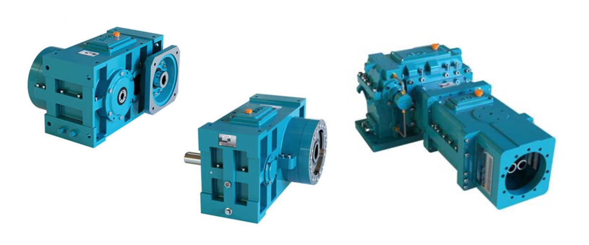
Ask a production engineer why their extrusion line is not hitting its target output rate, and the answer often lies not in the extruder screw design or the die geometry, but in a single number: the gear ratio of the gearbox. Gear ratio is one of the most fundamental parameters in a plastic extrusion drive system, yet it is routinely misunderstood, incorrectly specified, or simply accepted without question when a machine is commissioned. The gear ratio of your extruder gearbox determines the rotational speed of your extruder screw, which in turn directly controls the throughput rate, the melt temperature generated by shear heating, the melt pressure at the die, the quality and consistency of the extruded product, the torque demand on the gearbox, and the energy consumed per kilogram of plastic produced. Change the gear ratio, and every one of these performance parameters changes with it. This guide explains exactly what gear ratio is, how it is calculated, how it affects every aspect of plastic extrusion performance, how to select the right gear ratio for your specific material and application, and — critically — what goes wrong when the gear ratio is wrong. Whether you are commissioning a new extrusion line, upgrading an existing machine, troubleshooting a performance problem, or simply trying to understand your drive system better, this guide will give you the knowledge you need.
What is Gear Ratio? — The Fundamental Definition
Gear ratio is the numerical relationship between the rotational speed of the gearbox input shaft and the rotational speed of the gearbox output shaft. It expresses how many times the input shaft must rotate for the output shaft to complete one full revolution.
Gear Ratio Formula
Gear Ratio = Input Speed (RPM) / Output Speed (RPM)
Example: Motor speed = 1,450 RPM, Screw speed = 50 RPM
Gear Ratio = 1,450 / 50 = 29:1
This means the motor shaft rotates 29 times for every single rotation of the extruder screw.
In a plastic extrusion system, the input shaft of the gearbox is connected to the electric motor, and the output shaft is connected directly to the extruder screw. The gear ratio therefore defines the precise relationship between motor speed and screw speed across all operating conditions.
A higher gear ratio means the screw rotates more slowly relative to the motor. A lower gear ratio means the screw rotates faster relative to the motor. This seemingly simple relationship has profound and far-reaching consequences for every aspect of extrusion performance, as the following sections will demonstrate.
It is important to understand that gear ratio is a fixed mechanical property of the gearbox — it cannot be changed during operation. Once a gearbox with a specific gear ratio is installed on an extrusion line, the relationship between motor speed and screw speed is fixed by that ratio. Screw speed can only be changed by varying the motor speed using a variable speed drive. The gear ratio determines the range and scale of that speed variation.
How Gear Ratio is Calculated — Formulas and Worked Examples
Calculating the required gear ratio for an extruder gearbox is a straightforward process, but it requires accurate input data. The calculation must account for the motor rated speed, the required extruder screw speed range, and the relationship between motor speed and variable speed drive output.
Basic Gear Ratio Calculation
Gear Ratio Calculation Formula
Required Gear Ratio = Motor Rated Speed (RPM) / Maximum Required Screw Speed (RPM)
Worked Example 1 — HDPE Pipe Extrusion:
Motor rated speed: 1,450 RPM
Maximum screw speed: 80 RPM
Required gear ratio: 1,450 / 80 = 18.1 : 1 → Select 18:1 standard ratio
Worked Example 2 — Rigid PVC Profile Extrusion:
Motor rated speed: 1,450 RPM
Maximum screw speed: 30 RPM
Required gear ratio: 1,450 / 30 = 48.3 : 1 → Select 50:1 standard ratio
Worked Example 3 — LDPE Film Extrusion:
Motor rated speed: 1,450 RPM
Maximum screw speed: 120 RPM
Required gear ratio: 1,450 / 120 = 12.1 : 1 → Select 12:1 standard ratio
Calculating Output Torque from Gear Ratio
The gear ratio not only determines output speed — it also determines output torque. The relationship between input torque, output torque, and gear ratio is governed by the conservation of energy, subject to mechanical efficiency losses:
Torque Multiplication Formula
Output Torque (Nm) = Input Torque (Nm) x Gear Ratio x Gearbox Efficiency
Alternatively, from motor power:
Output Torque (Nm) = Motor Power (kW) x 9,550 / Output Speed (RPM) x Efficiency
Worked Example — 55 kW motor, gear ratio 25:1, output speed 58 RPM, efficiency 97%:
Output Torque = 55 x 9,550 / 58 x 0.97 = 8,795 Nm
This is the torque available at the extruder screw coupling at rated motor power.
Verifying Torque Against Material Requirements
Once the output torque is calculated, it must be verified against the torque demand of the extrusion process. The specific torque demand depends on the plastic material being processed, the screw diameter, the L/D ratio, and the throughput rate. As a general design rule, the calculated available output torque should exceed the estimated process torque demand by a service factor of at least 1.25 to 1.5 — providing a torque reserve for process variations, startup conditions, and material viscosity fluctuations.
The Effect of Variable Speed Drive on Effective Gear Ratio Range
Most modern extrusion lines use a variable speed drive (VSD or inverter) to control motor speed continuously from near zero up to the motor’s rated speed. This means the extruder screw speed can be varied continuously from near zero up to the maximum speed defined by the gear ratio. The gear ratio therefore defines the upper limit of screw speed, while the VSD controls the actual operating speed within that range.
This is an important practical point: if the gear ratio is too low (gives too high a maximum screw speed), the machine will rarely operate at the top of the VSD range, and will spend most of its time at low VSD output — which reduces motor efficiency and power factor. If the gear ratio is too high (gives too low a maximum screw speed), the machine cannot reach its required throughput rate even at full motor speed.
The Direct Relationship between Gear Ratio and Screw Speed
The most immediate and direct effect of gear ratio is on the rotational speed of the extruder screw. This relationship is exact and mechanical — there is no uncertainty or variability about it. At any given motor speed, the screw speed is always equal to the motor speed divided by the gear ratio.
| Gear Ratio | Screw Speed at 1,450 RPM Motor | Screw Speed at 1,000 RPM | Screw Speed at 700 RPM | Screw Speed at 400 RPM | Typical Application |
| 8 : 1 | 181 RPM | 125 RPM | 88 RPM | 50 RPM | High-speed LDPE film |
| 12 : 1 | 121 RPM | 83 RPM | 58 RPM | 33 RPM | PP / PE film, sheet |
| 16 : 1 | 91 RPM | 63 RPM | 44 RPM | 25 RPM | HDPE pipe, cable |
| 20 : 1 | 73 RPM | 50 RPM | 35 RPM | 20 RPM | HDPE / PP pipe |
| 25 : 1 | 58 RPM | 40 RPM | 28 RPM | 16 RPM | Mixed plastics, profiles |
| 32 : 1 | 45 RPM | 31 RPM | 22 RPM | 13 RPM | PVC soft, rubber |
| 40 : 1 | 36 RPM | 25 RPM | 18 RPM | 10 RPM | Rigid PVC profiles |
| 50 : 1 | 29 RPM | 20 RPM | 14 RPM | 8 RPM | Heavy PVC, rigid compounds |
| 63 : 1 | 23 RPM | 16 RPM | 11 RPM | 6 RPM | Very high viscosity materials |
This table makes clear why gear ratio selection is so critical. Selecting a gear ratio of 8:1 for a rigid PVC application would result in a screw speed over 180 RPM at full motor speed — far too fast for PVC, which degrades rapidly at excessive shear rates and temperatures. Conversely, selecting a gear ratio of 63:1 for a LDPE film line would limit the screw to just 23 RPM at full motor speed — far too slow for efficient thin-film production. The gear ratio must match the specific material and process requirements.
How Gear Ratio Affects Throughput Rate
Throughput rate — the kilograms of plastic produced per hour — is directly dependent on screw speed. In a single-screw extruder, the volumetric output rate increases approximately linearly with screw speed over the normal operating range. Doubling the screw speed approximately doubles the throughput, all other factors being equal.
The gear ratio therefore has a direct and proportional effect on the maximum achievable throughput rate. A gearbox with a lower gear ratio (higher output speed) enables a higher maximum screw speed, which enables a higher maximum throughput. A gearbox with a higher gear ratio (lower output speed) limits the maximum screw speed and therefore limits the maximum throughput rate.
Throughput Rate Relationship
Throughput (kg/h) = Screw Speed (RPM) x Specific Throughput Rate (kg/h per RPM)
The specific throughput rate depends on screw diameter, L/D ratio, and material.
For a typical 60mm diameter PE extruder: specific throughput ≈ 0.8 to 1.2 kg/h per RPM
At 60 RPM screw speed: throughput ≈ 48 to 72 kg/h
At 90 RPM screw speed: throughput ≈ 72 to 108 kg/h
At 120 RPM screw speed: throughput ≈ 96 to 144 kg/h
The gear ratio directly determines which of these speed ranges is achievable.
However, the relationship between gear ratio, screw speed, and throughput is not unlimited. Increasing screw speed beyond the optimal range for a given material generates disproportionately more shear heat, which raises melt temperature, potentially degrades the material, and may require the production speed to be reduced to maintain product quality. This is why the concept of a maximum screw speed specific to each material type is important — and why the gear ratio must be selected to make this optimum operating range accessible within the normal VSD operating range.
The Impact of Gear Ratio on Production Capacity Planning
When planning production capacity for a new extrusion line, the gear ratio selection is as important as the motor power selection. A motor that is powerful enough to drive the screw at the required torque, but paired with a gearbox whose gear ratio gives too low a screw speed, will be unable to deliver the required throughput even at full power. Conversely, a correctly sized motor paired with a gearbox whose ratio allows the required screw speed will consistently deliver the planned output.
This is why gear ratio selection must always be done in conjunction with throughput planning — not as an afterthought after the motor and extruder have already been selected.
How Gear Ratio Affects Torque and Motor Loading
The relationship between gear ratio and output torque is one of the most important — and most frequently misunderstood — aspects of extruder gearbox selection. A higher gear ratio does not simply reduce screw speed: it simultaneously amplifies the torque available at the output shaft, and changes the loading on the motor.
Higher Gear Ratio = More Output Torque from the Same Motor
At constant motor power, a higher gear ratio delivers more output torque at lower speed. This is directly relevant for processing high-viscosity plastics such as rigid PVC, HDPE with high molecular weight, and engineering polymers — materials that require very high torque at low screw speed to push the viscous melt through the barrel and die.
Consider two gearboxes driven by the same 75 kW motor at 1,450 RPM. One has a gear ratio of 20:1 (output speed 72.5 RPM), the other has a gear ratio of 40:1 (output speed 36.25 RPM). At 97% efficiency:
| Gearbox Parameter | Gear Ratio 20:1 | Gear Ratio 40:1 | Difference |
| Input Power | 75 kW | 75 kW | Same |
| Output Speed | 72.5 RPM | 36.25 RPM | 40:1 is 2x slower |
| Output Torque (at 97% eff.) | 9,582 Nm | 19,163 Nm | 40:1 gives 2x torque |
| Suitable for | HDPE, PE, PP, LLDPE | Rigid PVC, high MW polymers | Different materials |
This comparison shows that selecting the correct gear ratio is not just about getting the right screw speed — it is also about ensuring that the gearbox delivers sufficient torque for the material being processed. A gearbox with too low a gear ratio for a high-viscosity material will provide inadequate output torque, causing the motor to overload, the drive to trip on overcurrent, and the extruder to be unable to run at its designed output rate.
Motor Loading and Power Factor — Why Gear Ratio Affects Electrical Efficiency
When a motor-driven extruder operates with the correct gear ratio, the motor runs close to its rated load — typically at 75% to 95% of rated current. This is the operating range where motor efficiency and power factor are at their best. An incorrectly specified gear ratio that causes the motor to run either heavily underloaded or repeatedly at its overload limit both have negative effects on electrical efficiency and motor longevity.
How Gear Ratio Affects Melt Temperature and Product Quality
Of all the ways that gear ratio affects extrusion performance, its influence on melt temperature and product quality is arguably the most directly visible on the production floor — and the most costly when it goes wrong.
The Screw Speed–Shear Rate–Temperature Relationship
When the extruder screw rotates, it generates shear in the plastic melt between the screw flights and the barrel wall. This mechanical shear converts mechanical energy into heat — a phenomenon known as viscous or shear dissipation. The amount of shear heat generated increases with screw speed: faster screw rotation means higher shear rates, which means more heat generated in the melt.
The gear ratio directly controls the screw speed, and therefore directly controls the shear rate and the amount of shear heat generated. A gearbox with a gear ratio that allows excessively high screw speed for a given material will cause:
- Elevated Melt Temperature: Excessive shear heat raises the melt temperature above the optimal processing window, potentially causing thermal degradation, discolouration, burning, or loss of molecular weight in heat-sensitive materials such as PVC, PET, and certain engineering polymers.
- Surface Defects: Overheated melt can cause sharkskin, melt fracture, and surface roughness on the extruded product as the melt behaves erratically at the die exit.
- Dimensional Instability: Excessively hot melt has lower viscosity, which causes it to swell more after the die, making it more difficult to control extrudate dimensions during cooling.
- Material Degradation: In extreme cases, overheating causes irreversible chemical degradation — yellowing or browning of clear materials, loss of mechanical properties, generation of degradation gases, or complete material breakdown.
The Consequences of Too Low a Screw Speed (Too High a Gear Ratio)
The opposite problem — a gear ratio so high that screw speed is too low — has a different but equally damaging set of consequences:
- Insufficient Shear Heating: At very low screw speeds, insufficient shear heat is generated to achieve the target melt temperature. External barrel heaters must compensate, which increases energy consumption and reduces the uniformity of melt temperature across the barrel cross-section.
- Poor Mixing and Homogenisation: Low screw speed reduces the mixing action of the screw, potentially causing poor dispersion of additives, pigments, and fillers, and inadequate homogenisation of the melt.
- Low Throughput Rate: As discussed in Section 4, excessively low screw speed directly limits production output, reducing machine productivity and increasing cost per kilogram of product.
For most plastic extrusion applications, there is an optimal screw speed range that balances:- Sufficient shear heating to achieve target melt temperature without external barrel heating- Adequate mixing and homogenisation of the melt- Maximum throughput rate within acceptable melt temperature limits- Acceptable shear stress on shear-sensitive materialsThe gear ratio must be selected to place this optimal speed range within 60% to 95% of the motor’s rated speed on the VSD — ensuring efficient motor operation and adequate speed adjustment range.
How Gear Ratio Affects Energy Efficiency
Energy efficiency in plastic extrusion is increasingly important as energy costs rise and sustainability requirements tighten. The gear ratio has a direct and significant influence on the specific energy consumption of the extrusion process — measured in kilowatt-hours per kilogram of plastic produced (kWh/kg).
Operating Point Efficiency
The most energy-efficient operating point for an extrusion line is where the screw speed produces the maximum throughput rate that the material and process quality requirements will allow, with the motor operating close to its rated load. A gearbox with the correct gear ratio enables this efficient operating point to be reached consistently.
A gearbox with an incorrect gear ratio forces the machine to operate away from this optimal point:
- Too Low a Gear Ratio (Too High Screw Speed): The motor must be throttled back significantly on the VSD to prevent overheating the melt. This means the motor runs at a fraction of its rated speed and power, where motor and VSD efficiency are significantly reduced. The specific energy consumption (kWh/kg) increases.
- Too High a Gear Ratio (Too Low Screw Speed): The motor runs at full speed but the screw cannot reach the target throughput rate. To compensate, operators may push the process temperature higher using barrel heaters, increasing electrical energy consumption and melt degradation risk.
Gear Ratio and Specific Energy Consumption
| Gear Ratio Scenario | Motor Operating Point | Specific Energy (kWh/kg) | Assessment |
| Correctly matched ratio | 80 – 95% rated load | 0.18 – 0.25 kWh/kg | Optimal — best energy use |
| Ratio too low — VSD throttled | 30 – 50% rated load | 0.28 – 0.40 kWh/kg | Poor — 20–60% more energy |
| Ratio too high — max speed limited | 95 – 100% rated load, underproducing | 0.30 – 0.45 kWh/kg | Poor — less output per kWh |
The message from this table is clear: a correctly matched gear ratio is not just a mechanical consideration — it is an energy efficiency strategy. Replacing a mismatched gearbox with the correct ratio can reduce specific energy consumption by 20% to 40% in cases where the original gear ratio was poorly selected.
Gear Ratio Selection by Plastic Material Type
Different plastic materials have very different processing characteristics — melt viscosity, shear sensitivity, optimal processing temperature, and maximum shear rate — all of which translate into different optimal screw speed ranges and therefore different gear ratio requirements. The following table provides practical gear ratio guidance for the most common plastic extrusion materials:
| Plastic Material | Optimal Screw Speed Range (RPM) | Recommended Gear Ratio Range | Key Processing Consideration | Consequence of Wrong Ratio |
| LDPE / LLDPE | 80 – 150 RPM | 10:1 – 16:1 | High speed possible — low viscosity | Too slow: low output; too fast: melt fracture |
| HDPE | 50 – 100 RPM | 14:1 – 22:1 | Higher viscosity needs more torque | Too fast: overheating; too slow: insufficient mixing |
| PP (Polypropylene) | 60 – 100 RPM | 14:1 – 22:1 | Shear-sensitive — control melt temp | Too fast: degradation, discolouration |
| Rigid PVC (uPVC) | 15 – 35 RPM | 40:1 – 63:1 | Very shear/heat-sensitive; low speed essential | Too fast: severe thermal degradation, burning |
| Soft PVC | 30 – 60 RPM | 22:1 – 40:1 | More thermally stable than rigid PVC | Too fast: discolouration; too slow: poor fusion |
| PET | 60 – 100 RPM | 14:1 – 22:1 | Pre-drying essential; IV loss at high shear | Too fast: IV degradation, haze in film/sheet |
| ABS | 40 – 80 RPM | 18:1 – 32:1 | Moderate viscosity, good thermal stability | Too fast: surface defects; too slow: poor gloss |
| Nylon (PA6/PA66) | 40 – 80 RPM | 18:1 – 32:1 | Low melt viscosity — high output possible | Too fast: degradation; must pre-dry thoroughly |
| Polycarbonate (PC) | 30 – 60 RPM | 22:1 – 40:1 | Very heat-sensitive; low shear essential | Too fast: yellowing, molecular weight loss |
| PMMA (Acrylic) | 30 – 60 RPM | 22:1 – 40:1 | Shear-sensitive, clear product quality critical | Too fast: optical defects, surface haze |
| TPU / TPE | 40 – 70 RPM | 20:1 – 32:1 | Low to medium viscosity; shear affects hardness | Too fast: processing instability |
| WPC / Filled Compounds | 20 – 50 RPM | 28:1 – 50:1 | High viscosity due to filler content | Too fast: abrasive wear, heat buildup |
This table should be used as a starting point for gear ratio selection, not as a rigid specification. The actual optimal gear ratio for any specific application depends on the screw diameter, L/D ratio, screw design, barrel temperature profile, die geometry, and required throughput rate. For a precise recommendation, these factors should be evaluated by an experienced extrusion engineer or gearbox specialist.
Gear Ratio Selection by Extrusion Application
In addition to the material type, the specific extrusion application — the type of product being produced — places its own requirements on gear ratio selection. Different applications have different throughput priorities, dimensional tolerances, and surface quality requirements, all of which influence the optimal screw speed and therefore the gear ratio.
| Extrusion Application | Typical Screw Speed | Typical Gear Ratio | Application-Specific Consideration |
| Plastic Pipe (PE/PP) | 50 – 90 RPM | 16:1 – 25:1 | Wall thickness uniformity critical — consistent screw speed essential |
| Rigid PVC Pipe | 15 – 30 RPM | 45:1 – 63:1 | PVC thermal sensitivity demands low-speed, high-torque drive |
| Blown Film (LDPE/LLDPE) | 80 – 150 RPM | 10:1 – 16:1 | High output rate needed; melt strength determines upper speed limit |
| Cast Film / Sheet | 50 – 100 RPM | 14:1 – 22:1 | Surface quality and optical clarity sensitive to melt temperature |
| Cable Jacketing | 50 – 100 RPM | 14:1 – 22:1 | Tight dimensional tolerance — speed stability critical |
| PVC / PP Profiles | 20 – 50 RPM | 28:1 – 63:1 | Complex cross-section requires controlled melt flow — lower speed |
| Monofilament | 80 – 130 RPM | 11:1 – 18:1 | High draw ratio downstream — consistent melt temperature critical |
| Coating / Lamination | 80 – 150 RPM | 10:1 – 16:1 | Very thin coating layer — consistency and melt temperature key |
| Medical Tubing | 30 – 60 RPM | 22:1 – 40:1 | Tight dimensional and surface tolerances; low degradation risk |
| WPC Decking / Construction | 20 – 40 RPM | 35:1 – 63:1 | High filler load; very high torque needed at low speed |
Common Gear Ratio Mistakes and Their Consequences
Despite the clear importance of correct gear ratio selection, the same mistakes are made repeatedly across the plastic extrusion industry — often because gearboxes are selected without sufficient technical analysis of the process requirements, or because changes are made to the motor or process without recalculating the gear ratio implications. Here are the most damaging common errors:
Mistake 1 — Selecting Gear Ratio Based on a Previous Machine Without Checking
Engineers often specify the same gear ratio used on a previous machine of similar size, without verifying whether the new machine has the same motor speed, screw geometry, material type, and throughput requirements. Small differences in any of these factors can mean the inherited gear ratio is significantly wrong for the new application.
Consequence
Either insufficient throughput rate (if ratio is too high) or melt overheating and product defects (if ratio is too low).
Always calculate the required gear ratio from first principles for each new machine installation.
Mistake 2 — Using a Standard Catalogue Ratio Without Verification
Gearbox manufacturers offer a range of standard gear ratios — typically 8:1, 10:1, 12.5:1, 16:1, 20:1, 25:1, 31.5:1, 40:1, 50:1, 63:1 — and there is a natural tendency to select the nearest standard ratio to the calculated requirement without checking whether the rounding error is acceptable.
Consequence
A standard ratio 10% away from the ideal can place the motor operating point significantly off its optimal efficiency range, or require the screw to run at a speed that is not ideal for the material.
If the required ratio falls between two standard values, consider a custom ratio or re-optimise the motor speed to match a standard ratio exactly.
Mistake 3 — Changing Motor Without Recalculating Gear Ratio
A very common problem occurs when the original AC motor is replaced with a higher-speed motor (for example, replacing a 4-pole 1,450 RPM motor with a 2-pole 2,900 RPM motor), or when the motor pulley ratio is changed in a belt-driven arrangement, without recalculating the effect on screw speed.
Consequence
Doubling the motor speed with the same gear ratio doubles the screw speed — which can catastrophically overspeed the screw for many materials, causing melt overheating, product degradation, and potential mechanical damage.
Any change to motor speed must be followed by a full review and recalculation of the gear ratio and screw speed.
Mistake 4 — Ignoring Torque Requirements When Selecting for Speed
Some engineers select the gear ratio purely to achieve the target screw speed, without verifying whether the gearbox and motor combination will deliver sufficient torque for the material at that speed. This is particularly common when high-viscosity materials are introduced onto a line originally designed for lower-viscosity materials.
Consequence
Insufficient torque causes the motor to overload and trip, the VSD to fault on overcurrent, or the extruder to run at reduced speed with poor productivity.
Always calculate the required output torque for the most demanding material at the required screw speed, and verify that the gearbox output torque rating exceeds this by the required service factor.
Mistake 5 — Not Accounting for Motor Derating at High Ambient Temperature
Electric motors lose output power when operated above their rated ambient temperature. A motor rated at 75 kW at 40°C ambient will only deliver approximately 67 kW at 50°C ambient. If this derating is not accounted for in the torque calculation, the available output torque at the gearbox will be lower than calculated.
Consequence
Gearbox and motor operate closer to — or beyond — their limits, reducing service life and increasing breakdown risk.
Always apply an ambient temperature derating factor when calculating motor output power in hot environments.
How to Change or Optimise the Gear Ratio on an Existing Line
If you have identified that the gear ratio on an existing extrusion line is incorrect — either from the symptoms described in Section 10 or from a systematic performance review — there are several approaches to optimising it without necessarily replacing the entire gearbox:
- Gearbox Replacement: The most straightforward solution — replace the existing gearbox with a correctly specified unit of the required gear ratio. This ensures all other gearbox parameters (torque rating, thrust bearing capacity, service factor) are also correctly matched to the application.
- Gear Set Replacement within Existing Housing: For gearboxes with a modular design, it may be possible to replace only the internal gear sets to achieve a different gear ratio, while retaining the existing housing and bearings. This is more economical than full gearbox replacement but requires a detailed engineering assessment to confirm feasibility.
- Motor Pulley / Belt Drive Adjustment: On extrusion lines with a belt-and-pulley drive between the motor and gearbox, the effective gear ratio can be adjusted by changing the motor pulley diameter. This is a low-cost option but is limited in range and may reduce drive efficiency.
- Motor Speed Re-parametrisation: On lines with a variable speed drive, the maximum motor speed can be adjusted through the VSD parameters to effectively change the maximum screw speed without hardware changes. This approach has limitations — operating the motor above its rated frequency reduces available torque — but can be a useful interim solution.
- Motor Replacement: If the existing motor speed is the root cause of the gear ratio mismatch, replacing the motor with a different pole count (and therefore different rated speed) may be more appropriate than changing the gearbox, particularly if the gearbox is new or in good condition.
Before committing to any gear ratio change on an existing line, carry out a full drive train audit:
- Measure the actual screw speed at various VSD settings and compare to what the gear ratio calculation predicts.
- Measure the motor current at typical operating conditions and compare to the motor nameplate current.
- Record the melt temperature at the die at current operating conditions.
- Calculate the ideal gear ratio from the material requirements and required throughput.
- Assess the gap between the current and ideal ratio, and select the most appropriate correction method.
Our Extruder Gearbox Range — Right Gear Ratio for Every Application
Selecting the correct gear ratio is one of the most important decisions in specifying an extruder gearbox — and it is one we take seriously for every customer inquiry. Our range of extruder helical gearboxes covers every standard gear ratio from 8:1 to 80:1, with custom ratios available for non-standard applications, across a torque range from 500 Nm to 250,000 Nm output.
Every gearbox in our range is designed and built specifically for plastic extrusion duty — with precision-ground helical gears, purpose-rated thrust bearing assemblies, multi-stage shaft sealing for dusty extrusion environments, and integrated thermal management for continuous-duty operation. We do not supply modified standard industrial gearboxes for extrusion applications — we supply extruder-specific designs that are engineered to handle the unique combination of high torque, axial thrust, and continuous duty that plastic extrusion demands.
Our Gear Ratio Selection Service
- Free Gear Ratio Calculation: Provide us with your motor data (power, rated speed, frame size), your required screw speed range, and your plastic material type and we will calculate the exact gear ratio, output torque, and service factor for your application.
- Full Drive Train Review: For new extrusion line projects, we offer a complete drive train review service — assessing motor selection, gear ratio, gearbox torque and thrust bearing rating, and VSD parametrisation — to ensure every element of the drive system is optimally matched.
- Upgrade Assessment for Existing Lines: If you are experiencing performance problems that may be related to an incorrect gear ratio, we can assess your existing installation and recommend the most cost-effective solution — from gear set replacement to full gearbox upgrade.
- Application Data Library: Our engineering database contains gear ratio recommendations and drive train specifications for over 200 plastic material and application combinations — enabling fast and accurate specification for most standard extrusion applications.
Contact our technical team today to discuss your gear ratio requirements and receive a free, no-obligation specification recommendation for your extrusion application.
Frequently Asked Questions (FAQs)
Q1. What is the most common gear ratio used in plastic extrusion?
The most common gear ratios in plastic extrusion are 16:1, 20:1, and 25:1, which cover the majority of standard HDPE, LDPE, PP, and general-purpose extrusion applications with a 4-pole 1,450 RPM motor. These ratios give screw speeds of approximately 90, 72, and 58 RPM respectively at full motor speed — within the optimal range for most common polyolefin materials. For PVC extrusion, ratios of 40:1 to 63:1 are more typical. For high-speed film extrusion with LDPE or LLDPE, ratios of 10:1 to 14:1 are used.
Q2. Can I run my extruder at a higher throughput rate by simply increasing the VSD frequency above 50 Hz?
Many variable speed drives allow the output frequency to be increased above 50 Hz (which over speeds the motor above its rated speed) to achieve higher throughput. While this is technically possible in the short term, it is not recommended as a routine operating practice. Running a motor above its rated frequency reduces the available torque (torque decreases in the field-weakening region above rated speed) and increases mechanical stress on motor bearings and windings. The correct solution to an insufficient throughput rate is to review the gear ratio and consider a gearbox with a lower gear ratio, not to routinely overspeed the motor.
Q3. How does gear ratio affect the minimum stable screw speed?
The minimum stable screw speed is the lowest speed at which the extruder screw can rotate while still maintaining a consistent, well-mixed melt flow through the barrel and die. This minimum speed is a function of the extruder screw design and the material being processed — it is not directly set by the gear ratio. However, a gearbox with a very high gear ratio (e.g. 80:1) gives very fine speed control at low screw speeds, which can be beneficial for startup procedures and slow-speed purging operations. A gearbox with a low gear ratio may pass through the minimum stable screw speed very rapidly as motor speed is increased from zero, making slow-speed operation more difficult to control.
Q4. If my extruder is running too hot, can changing the gear ratio fix it?
Yes — if the root cause of excessive melt temperature is an incorrect (too low) gear ratio that is forcing the screw to run faster than optimal for the material, then fitting a gearbox with a higher gear ratio to reduce screw speed will reduce shear heating and lower melt temperature. However, before changing the gear ratio, confirm that the high melt temperature is actually caused by excessive screw speed and shear heating, rather than by incorrect barrel temperature settings, insufficient barrel cooling, or an unsuitable screw design. A temperature profile analysis along the barrel length, combined with screw speed and motor current data, will help identify the true root cause.
Q5. What happens if I operate my extruder gearbox at a higher motor speed than it is rated for?
Operating the gearbox input shaft above its rated maximum speed can cause several problems: increased centrifugal forces on bearing rolling elements leading to accelerated bearing wear; higher gear peripheral speeds resulting in inadequate oil film thickness at gear mesh contacts causing scuffing and pitting; increased noise and vibration; elevated oil temperature from higher churning and windage losses; and potential failure of shaft seals due to higher surface speeds. Never exceed the maximum input speed stated on the gearbox nameplate. If higher screw speeds are required, the correct solution is to change to a gearbox with a lower gear ratio, not to overspeed the existing gearbox.
Conclusion
Gear ratio is far more than a number on a gearbox nameplate. It is the fundamental parameter that links your motor’s rotational speed to your extruder screw’s operating speed — and in doing so, it directly determines your throughput rate, your melt temperature, your product quality, your torque availability, your energy efficiency, and your gearbox service life. Get the gear ratio right, and your extrusion line will perform consistently and efficiently. Get it wrong, and every other engineering decision on your line will be fighting against that fundamental mismatch.
The key takeaways from this guide are straightforward: always calculate the required gear ratio from the motor speed and required screw speed before specifying the gearbox; verify that the output torque is sufficient for your most demanding material at service factor; use the material and application selection tables in this guide as a cross-reference; and do not accept an incorrect gear ratio as a permanent operating condition — the consequences in lost efficiency, product quality, and gearbox life are too significant.
Whether you are specifying a gearbox for a new extrusion line, troubleshooting a performance problem on an existing machine, or planning a product range change that will require different processing speeds, the gear ratio analysis is always the right starting point. The investment in getting it right — in engineering time, in correct gearbox selection, and in precise drive train design — pays back many times over in production performance, energy savings, and reduced maintenance cost over the life of the machine.
