
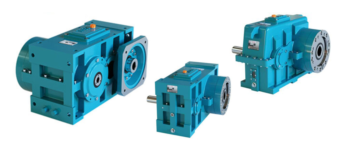
Choosing a gearbox for a plastic extruder is one of the most consequential procurement decisions in any extrusion plant. Get it right and you have a drive system that runs reliably, efficiently, and quietly for fifteen to twenty years — processing every material you put through it without complaint, without downtime, and without maintenance surprises. Get it wrong and you have years of undersized torque, overheating motors, premature bearing wear, material quality problems, and the recurring cost of emergency replacements that always seem to happen at the worst possible time. Yet in many plants, gearbox selection is treated as a secondary decision — something that happens after the motor and extruder screw have been chosen, with the gearbox selected primarily on price or on the basis of whatever the previous machine used. Engineers who would never specify a motor or screw design without careful calculation routinely select a gearbox from a catalogue based on a rough size match. This approach works until it doesn’t — and when it fails, the consequences are disproportionately expensive. This complete selection guide eliminates the guesswork from extruder gearbox selection. It takes you through every selection parameter in the order you should evaluate it — from the fundamental question of gear type, through gear ratio and torque calculation, to service factor, thrust bearing, cooling, seal specification, and physical installation requirements. At every step it provides worked examples, reference tables, and decision tools that allow you to make a technically correct selection for any plastic extruder application. Whether you are specifying a new line, replacing a failed unit, or upgrading an existing machine, this guide gives you the framework to select with confidence.
The Selection Framework – 10 Parameters in the Right Order
Extruder gearbox selection is not a single decision — it is a sequence of ten interdependent decisions, each of which depends on the answers to the ones before it. The order matters: calculating torque before fixing the gear ratio leads to errors; specifying cooling before calculating heat load leads to under- or over-provision. The framework below organises the ten selection parameters in the sequence that produces the most reliable, correctly matched result.
| Step | Selection Parameter | What You Are Deciding | Key Input Required |
| 1 | Gear Type | Helical, worm, bevel — which is right? | Application type, duty cycle, efficiency requirement |
| 2 | Required Screw Speed | Minimum and maximum RPM the screw must achieve | Material type, screw diameter, throughput target |
| 3 | Gear Ratio | The speed reduction ratio between motor and screw | Motor speed (RPM), required screw speed (RPM) |
| 4 | Output Torque Requirement | The torque the gearbox must deliver at the output shaft | Motor power (kW), output speed (RPM), efficiency |
| 5 | Service Factor | The safety margin above the calculated torque demand | Duty cycle, material type, startup conditions |
| 6 | Thrust Bearing Capacity | The axial load rating for the extruder screw reaction | Screw diameter, maximum die/back pressure |
| 7 | Cooling System | How the gearbox heat will be removed | Heat load (kW), ambient temperature, water availability |
| 8 | Seal Specification | The shaft seal type for the operating environment | Dust level, oil temperature, secondary seal requirement |
| 9 | Physical Fit and Mounting | Dimensions, shaft sizes, and mounting interface | Machine frame drawings, coupling details, access space |
| 10 | Final Verification | Confirming all parameters are consistent and complete | All above inputs cross-checked against each other |
Working through all ten steps for every new gearbox selection takes approximately two to three hours of engineering time — a trivial investment compared to the cost of an incorrect selection. Each step is explained in full detail in the sections that follow, with worked examples throughout.
Step 1 – Choose the Gear Type
The first and most fundamental selection decision is the gear type. For plastic extruder applications, this decision is, in the vast majority of cases, straightforward — the helical gearbox is the correct choice. However, understanding why it is the correct choice, and understanding the narrow circumstances where alternatives might be considered, is essential background knowledge for any gearbox selector.
Why the Helical Gearbox is the Standard for Plastic Extrusion
The helical gearbox dominates plastic extrusion because it uniquely satisfies all the requirements of continuous high-torque extrusion duty simultaneously: it is highly efficient (95 to 98 percent), handles very high continuous torque through rolling contact gear tooth engagement, produces low noise and vibration (critical for product quality consistency), can be built with an integrated thrust bearing assembly to absorb screw axial forces, and provides a long service life under the continuous high-load conditions of production extrusion. No other common gear type matches this combination of characteristics. A comprehensive comparison of the helical gearbox against the worm gearbox is provided in our dedicated comparison guide.
Gear Type Selection Decision Matrix
| Evaluation Criterion | Helical | Worm | Bevel-Helical | Spur | Verdict for Extrusion |
| Efficiency (%) | 95 – 98% | 50 – 90% | 94 – 97% | 93 – 96% | Helical wins |
| Continuous torque capacity | Very High | Moderate | High | High | Helical wins |
| Noise and vibration | Very Low | Low | Low | Medium-High | Helical wins |
| Built-in thrust capacity | Yes | No | No | No | Helical only |
| Compactness | Good | Excellent | Good | Good | Worm wins |
| Service life (extrusion) | 15 – 20+ yr | 3 – 8 yr | 10 – 15 yr | 8 – 12 yr | Helical wins |
| Initial purchase cost | Higher | Lower | Higher | Moderate | Worm wins |
| Total life-cycle cost | Lowest | Highest | Moderate | Moderate | Helical wins |
| Overall for extrusion | Recommended | Not suitable | Specialised | Not preferred | Use Helical |
The verdict is clear: for any continuous-duty plastic extrusion application, specify a helical gearbox. The only situations where an alternative might be considered are small laboratory extruders below 5 kW (where compactness may justify a worm unit’s efficiency penalty), and directional power transmission applications requiring a 90-degree shaft arrangement (where a bevel-helical combination may be appropriate). For all standard production extrusion, helical is the specification.
Step 2 – Determine the Required Screw Speed Range
Before the gear ratio can be calculated, the required screw speed range must be clearly defined. This is not a single number — it is a range from the minimum operating speed (relevant for startup and slow production) to the maximum operating speed (relevant for maximum throughput). Both ends of the range matter for gearbox selection.
How to Determine the Required Screw Speed
The required maximum screw speed is determined by three factors working together: the plastic material’s maximum shear rate tolerance, the extruder screw geometry (diameter and L/D ratio), and the required maximum throughput rate. For most standard applications, the extruder manufacturer specifies the rated screw speed — this should be the starting point. If designing from scratch, the following reference ranges provide practical guidance:
| Plastic Material | Min. Screw Speed (RPM) | Max. Screw Speed (RPM) | Optimal Operating Range | Governing Constraint |
| LDPE / LLDPE | 10 | 150 | 80 – 130 RPM | Melt quality, film stability |
| HDPE (standard MW) | 10 | 100 | 50 – 90 RPM | Melt temperature limit |
| HDPE (high MW) | 5 | 70 | 30 – 60 RPM | High viscosity, torque limit |
| PP (polypropylene) | 10 | 100 | 60 – 90 RPM | Melt temperature sensitivity |
| Soft PVC | 10 | 60 | 30 – 55 RPM | Thermal stability window |
| Rigid PVC (uPVC) | 5 | 35 | 15 – 30 RPM | Severe thermal sensitivity |
| PET | 10 | 100 | 60 – 90 RPM | IV retention, pre-dry essential |
| ABS | 10 | 80 | 40 – 70 RPM | Melt quality, surface finish |
| Polycarbonate (PC) | 5 | 60 | 30 – 55 RPM | Molecular weight retention |
| Nylon (PA6 / PA66) | 10 | 80 | 50 – 75 RPM | Moisture sensitivity, pre-dry |
| TPU / TPE | 10 | 70 | 40 – 65 RPM | Shear sensitivity, melt temp |
| WPC / Filled compounds | 5 | 50 | 20 – 45 RPM | High viscosity, filler loading |
When the machine will process more than one material type, always use the most demanding material to define the speed range. The maximum screw speed for selection purposes should be the speed at which the most demanding material can be processed without quality degradation — not the physical maximum speed of the screw geometry.
Step 3 – Calculate the Required Gear Ratio
With the required maximum screw speed established and the motor’s rated speed known, the required gear ratio is calculated directly from the ratio of motor speed to screw speed. This is a simple but critical calculation — rounding errors or approximations at this stage propagate through all subsequent calculations.
Gear Ratio Calculation
Required Gear Ratio = Motor Rated Speed (RPM) / Maximum Required Screw Speed (RPM)
WORKED EXAMPLE 1 — HDPE Pipe Extrusion, 90mm Screw:
Motor rated speed: 1,450 RPM (4-pole AC motor at 50 Hz)
Maximum screw speed: 80 RPM
Required gear ratio: 1,450 / 80 = 18.1 : 1
Standard ratio to select: 18 : 1 (closest standard below calculated value)
Actual max screw speed: 1,450 / 18 = 80.6 RPM ✓ adequate
WORKED EXAMPLE 2 — Rigid PVC Profile Extrusion, 65mm Screw:
Motor rated speed: 1,450 RPM
Maximum screw speed: 28 RPM
Required gear ratio: 1,450 / 28 = 51.8 : 1
Standard ratio to select: 50 : 1 (check if adequate) or 63 : 1
At 50:1: max screw speed = 1,450 / 50 = 29 RPM ✓ marginally adequate
At 63:1: max screw speed = 1,450 / 63 = 23 RPM ✗ too slow for full output
Select 50 : 1
WORKED EXAMPLE 3 — LDPE Blown Film, 120mm Screw:
Motor rated speed: 1,450 RPM
Maximum screw speed: 120 RPM
Required gear ratio: 1,450 / 120 = 12.1 : 1
Standard ratio to select: 12 : 1
Standard Gear Ratio Series – Available Options
Gearbox manufacturers produce helical extruder gearboxes in standard gear ratio series. Understanding what standard ratios are available allows the selector to choose the nearest standard that meets the requirement, or to identify when a custom ratio is necessary.
| Standard Gear Ratio | Screw Speed at 1450 RPM | Screw Speed at 960 RPM | Primary Application | Gear Stages |
| 8 : 1 | 181 RPM | 120 RPM | High-speed LDPE/LLDPE film | 2-stage |
| 10 : 1 | 145 RPM | 96 RPM | Fast PE film, coating lines | 2-stage |
| 12.5 : 1 | 116 RPM | 77 RPM | PE film, PP sheet | 2-stage |
| 16 : 1 | 91 RPM | 60 RPM | HDPE pipe, cable jacketing | 2-stage |
| 20 : 1 | 73 RPM | 48 RPM | HDPE / PP pipe, profiles | 2-stage |
| 25 : 1 | 58 RPM | 38 RPM | Mixed plastics, ABS, profiles | 2-stage |
| 31.5 : 1 | 46 RPM | 30 RPM | Soft PVC, TPU, compounds | 2-stage |
| 40 : 1 | 36 RPM | 24 RPM | Rigid PVC pipe, profiles | 3-stage |
| 50 : 1 | 29 RPM | 19 RPM | Heavy PVC, rigid compounds | 3-stage |
| 63 : 1 | 23 RPM | 15 RPM | Very high viscosity materials | 3-stage |
| 80 : 1 | 18 RPM | 12 RPM | Ultra-high viscosity, WPC | 3-stage |
When a Custom Gear Ratio is Required
If the calculated ideal gear ratio falls between two standard values and neither standard option provides an acceptable screw speed within 5 to 8 percent of the target, a custom gear ratio should be specified. Custom ratios typically add 8 to 15 weeks to delivery lead time and 15 to 25 percent to cost compared to standard ratio units. In most cases, the preferred alternative is to re-optimise the motor speed selection (using a different motor pole count or a belt drive ratio) to make a standard gear ratio work exactly, rather than ordering a custom unit.
Step 4 – Calculate the Required Output Torque
Output torque is the most important specification parameter for an extruder gearbox — more important than size, more important than weight, and more important than price. The gearbox’s output torque determines whether it can actually drive the extruder screw through the most viscous material at the highest required output rate.
Torque Calculation from Motor Power
Output Torque Calculation Formula
Output Torque (Nm) = Motor Power (kW) x 9,550 / Output Speed (RPM) x Efficiency
Where: Output Speed (RPM) = Motor Speed (RPM) / Gear Ratio
Efficiency = gearbox mechanical efficiency (use 0.97 for helical)
WORKED EXAMPLE — 110 kW motor, gear ratio 20:1, 1,450 RPM motor:
Output speed = 1,450 / 20 = 72.5 RPM
Output torque = 110 x 9,550 / 72.5 x 0.97
Output torque = 1,050,500 / 72.5 x 0.97
Output torque = 14,490 x 0.97 = 14,055 Nm
This is the maximum torque available at the gearbox output shaft at rated motor power.
The gearbox rated output torque must be at least equal to this value (plus service factor — see Step 5).
Torque Requirements by Screw Diameter and Material
The required output torque also depends on the extruder screw diameter and the material being processed. The following reference table provides indicative torque requirements for the most common combinations — use these values to cross-check your motor-power-based calculation and to verify that the motor is appropriately sized for the screw diameter and material:
| Screw Diameter | Material | Typical Screw Speed | Required Output Torque | Indicative Motor Power |
| 50 mm | HDPE | 60 – 80 RPM | 2,500 – 5,000 Nm | 18.5 – 37 kW |
| 50 mm | Rigid PVC | 20 – 30 RPM | 5,000 – 10,000 Nm | 11 – 22 kW |
| 65 mm | HDPE | 60 – 90 RPM | 5,000 – 10,000 Nm | 37 – 75 kW |
| 65 mm | Rigid PVC | 20 – 30 RPM | 10,000 – 20,000 Nm | 22 – 45 kW |
| 75 mm | HDPE | 60 – 90 RPM | 8,000 – 16,000 Nm | 55 – 110 kW |
| 75 mm | Rigid PVC | 20 – 30 RPM | 16,000 – 32,000 Nm | 37 – 75 kW |
| 90 mm | HDPE | 50 – 80 RPM | 12,000 – 25,000 Nm | 75 – 160 kW |
| 90 mm | Rigid PVC | 15 – 25 RPM | 25,000 – 55,000 Nm | 55 – 110 kW |
| 110 mm | HDPE | 50 – 75 RPM | 20,000 – 45,000 Nm | 110 – 250 kW |
| 110 mm | Rigid PVC | 15 – 25 RPM | 45,000 – 100,000 Nm | 90 – 185 kW |
| 130 mm | HDPE | 40 – 65 RPM | 35,000 – 75,000 Nm | 160 – 400 kW |
If your motor-based torque calculation gives a value significantly different from the material-based reference in this table, investigate the discrepancy before proceeding. Either the motor is not appropriately sized for the screw and material combination, or the operating conditions are not as expected. Resolving the discrepancy at selection stage is far less costly than discovering it after commissioning.
Step 5 – Apply the Correct Service Factor
The service factor is the safety multiplier applied to the calculated torque demand before selecting the gearbox rated output torque. It is one of the most important — and most frequently inadequate — parameters in extruder gearbox selection. Many specifications use a blanket service factor of 1.25 for all applications, which is insufficient for demanding materials and operating conditions.
Service Factor Selection Table
| Application Condition | Minimum Service Factor | Justification |
| Single material, steady load, continuous run | 1.25 | Minimum acceptable for continuous extrusion |
| Two to three materials, occasional changeover | 1.40 | Viscosity variation between material batches |
| Multiple materials, frequent changeovers | 1.50 | Variable torque demand profile |
| HDPE high molecular weight or PP filled | 1.50 | Higher than average viscosity with spikes |
| Rigid PVC pipe or profile (counter-rotating twin) | 1.75 | High viscosity plus cold-start peak torque |
| Rigid PVC, frequent cold starts without warm-up | 2.00 | Extreme cold-start torque peaks |
| Compounding with hard filler loading (> 30%) | 2.00 | Unpredictable viscosity spikes |
| Engineering polymers (PC, PMMA) sensitive processes | 2.00 | Shear sensitivity and viscosity variability |
| Twin screw compounding — variable fill and recipe | 2.00 – 2.25 | High variability, frequent stops and starts |
| Critical production line — maximum uptime required | 2.25 – 2.50 | Generous margin for any unforeseen condition |
How Service Factor Translates to Minimum Gearbox Rated Torque
Minimum Gearbox Rated Torque Calculation
Minimum Gearbox Rated Output Torque (Nm) = Calculated Output Torque (Nm) x Service Factor
WORKED EXAMPLE — From Step 4: Calculated torque = 14,055 Nm
Application: HDPE pipe extrusion with occasional material grade changes
Service Factor selected: 1.50
Minimum gearbox rated torque = 14,055 x 1.50 = 21,083 Nm
Select a gearbox with rated output torque of at least 21,083 Nm.
Standard catalogue torque rating: 22,500 Nm (next standard size above 21,083 Nm) ✓
Step 6 – Verify the Thrust Bearing Capacity
The thrust bearing capacity is a parameter unique to extruder gearboxes that distinguishes them from standard industrial gearboxes. The thrust bearing must absorb the full axial reaction force generated as the extruder screw pushes plastic melt towards the die. Failing to verify this capacity — or selecting a standard industrial gearbox without adequate thrust provisions — is one of the most common and most damaging selection errors in plastic extrusion.
Estimating the Required Thrust Bearing Capacity
The axial screw force depends on the screw tip area, the melt pressure at the screw tip, and any additional dynamic contributions from material viscosity and screw geometry. A conservative estimate uses the maximum melt pressure and the full screw tip cross-sectional area:
Axial Thrust Force Estimation
Axial Force (kN) = Maximum Melt Pressure (MPa) x Screw Tip Area (cm²) / 10
Screw Tip Area (cm²) = π/4 x (Screw Diameter in cm)²
WORKED EXAMPLE — 90mm screw, maximum melt pressure 350 bar (35 MPa):
Screw tip area = π/4 x (9.0)² = 63.6 cm²
Axial force = 35 x 63.6 / 10 = 222 kN
The gearbox thrust bearing capacity must exceed 222 kN in this application.
Select a gearbox with thrust bearing rating ≥ 222 kN (with safety margin of at least 1.3x).
Reference maximum melt pressures by material:
LDPE / LLDPE: 150 – 250 bar Rigid PVC: 200 – 450 bar
HDPE: 200 – 350 bar PC / PMMA: 200 – 400 bar
PP: 150 – 300 bar WPC: 200 – 500 bar
Thrust Bearing Capacity Reference by Screw Diameter
| Screw Diameter (mm) | Screw Tip Area (cm²) | Typical Max Thrust Force | Min. Thrust Bearing Rating | Application Note |
| 45 mm | 15.9 cm² | 50 – 120 kN | 80 – 160 kN | Standard HDPE/PP |
| 60 mm | 28.3 cm² | 90 – 220 kN | 120 – 300 kN | Standard medium |
| 75 mm | 44.2 cm² | 140 – 340 kN | 185 – 445 kN | Large HDPE / PVC |
| 90 mm | 63.6 cm² | 200 – 490 kN | 260 – 640 kN | Heavy duty extrusion |
| 110 mm | 95.0 cm² | 300 – 730 kN | 390 – 950 kN | Large pipe / profile |
| 130 mm | 132.7 cm² | 420 – 1,020 kN | 545 – 1,330 kN | Large industrial line |
| 150 mm | 176.7 cm² | 560 – 1,360 kN | 730 – 1,770 kN | Very large extruder |
Critical Warning — Never Use a Standard Industrial Gearbox on an Extruder
Standard industrial helical gearboxes are NOT designed for the sustained high axial loads of extrusion duty.
They are designed primarily for radial loading, with limited axial capacity from their standard bearings.
Using a standard industrial gearbox on an extruder will result in:
— Rapid failure of the output shaft bearings within months to a few years
— Progressive axial shaft movement causing screw-barrel contact
— Potential destruction of both the barrel and the extruder screw
Always specify a gearbox designed and rated specifically for extruder duty.
Step 7 – Select the Cooling System
Once the gear ratio, output torque, and service factor are established, the gearbox heat load can be calculated and the appropriate cooling system selected. The cooling system selection depends on three inputs: the calculated heat load, the ambient temperature at the installation location, and the availability of cooling water.
Calculating Heat Load
Gearbox Heat Load Calculation
Heat Load (kW) = Motor Power (kW) x (1 – Gearbox Efficiency)
For helical gearbox at 97% efficiency:
Heat Load = Motor Power x 0.03
Examples:
55 kW motor: 55 x 0.03 = 1.65 kW heat generation
110 kW motor: 110 x 0.03 = 3.3 kW heat generation
200 kW motor: 200 x 0.03 = 6.0 kW heat generation
400 kW motor: 400 x 0.04 = 16.0 kW heat generation (3-stage: ~96% eff.)
Cooling System Selection Guide
| Motor Power Range | Heat Load (kW) | Ambient Temp. | Water Available? | Recommended Cooling System |
| Up to 30 kW | Up to 0.9 kW | Below 35°C | Either | Natural convection — housing fins |
| Up to 30 kW | Up to 0.9 kW | 35 – 50°C | No | Air-blast fan cooling |
| 30 – 90 kW | 0.9 – 2.7 kW | Below 45°C | Yes | Internal water cooling coil |
| 30 – 90 kW | 0.9 – 2.7 kW | 45 – 60°C | Yes | Larger cooling coil; synthetic oil |
| 90 – 200 kW | 2.7 – 6.0 kW | Below 50°C | Yes | Standard internal cooling coil |
| 90 – 200 kW | 2.7 – 6.0 kW | 50 – 65°C | Yes | Forced-feed with external cooler |
| 200 – 400 kW | 6.0 – 12.0 kW | Any | Yes | Forced-feed with external oil cooler |
| 400 kW and above | 12.0 kW+ | Any | Yes | Forced-feed with large external cooler |
| Any power | Any | Any | No | Air-cooled external oil cooler + fan |
Step 8 – Specify the Seal and Environmental Protection
The shaft seal specification is a function of two factors: the operating temperature of the gearbox oil (which determines the thermal demand on the seal material) and the environmental contamination level at the installation (which determines the need for secondary sealing and dust exclusion). For plastic extrusion applications, both factors typically point towards an enhanced sealing specification compared to standard industrial gearboxes.
Seal Material Selection
| Operating Condition | Oil Temp Range | Recommended Seal Material | Additional Provision |
| Standard extrusion, clean environment | 40 – 70°C | NBR (minimum) or FKM | Standard single lip seal acceptable |
| Standard extrusion, dusty environment | 40 – 70°C | FKM primary lip seal | V-ring or labyrinth secondary seal required |
| Hot running gearbox (70 – 90°C oil) | 70 – 90°C | FKM (Viton) — mandatory | Secondary seal strongly recommended |
| High-dust extrusion (glass fibre, CaCO3) | Any | FKM primary lip seal | Labyrinth + V-ring double exclusion system |
| Very hot environment or tropical climate | 70 – 100°C | FKM — mandatory | Forced-feed lubrication to cool seal area |
| Corrosive environment (chemicals, salt air) | Any | FKM with PTFE lip | Stainless shaft sleeve at seal contact |
For all plastic extrusion applications, we recommend specifying FKM (Viton) seals as a minimum — not just for hot-running situations, but as standard practice. The marginal cost difference between NBR and FKM seals (typically Rs 500 to 2,000 per seal) is negligible compared to the service life advantage — FKM seals in an extrusion environment typically provide 3 to 5 times the service life of NBR seals, significantly reducing both maintenance frequency and the risk of oil contamination from early seal failure.
Step 9 – Check Physical Fit and Mounting Configuration
A gearbox that is correctly specified in all technical parameters but does not physically fit the machine is still the wrong gearbox. Physical fit verification should be completed before finalising the order, not after delivery. The following dimensions and parameters must be confirmed against the machine’s physical requirements.
| Parameter to Check | What to Measure / Verify | Consequence of Mismatch |
| Centre height (shaft height) | Distance from gearbox mounting foot to output shaft centreline | Extruder screw shaft misaligned; cannot couple |
| Output shaft diameter | Shaft diameter and length at coupling interface (ISO tolerance) | Coupling does not fit; must be rebored or replaced |
| Output shaft type | Solid shaft, hollow shaft, or flanged output | Coupling type mismatch; incompatible with extruder |
| Input shaft diameter | Motor coupling side — diameter and length | Motor coupling does not fit gearbox input |
| Mounting foot configuration | Foot pattern, bolt hole size, and spacing | Gearbox cannot be bolted to machine base |
| Overall dimensions (LxWxH) | Gearbox envelope fits within machine frame opening | Gearbox physically too large for installation space |
| Cooling coil connections | Water inlet/outlet port size and location | Cannot connect plant cooling water supply |
| Oil fill/drain ports | Location accessible with gearbox in situ | Cannot change oil without removing gearbox |
| Shaft rotation direction | Output shaft rotation must drive screw in correct direction | Screw runs backwards — product ejected from feed |
| Gear ratio direction convention | Confirm ratio = input/output (not output/input) | Gear ratio error — screw runs at wrong speed |
When replacing a failed gearbox on an existing machine, always obtain the dimensional drawings of the failed unit from the machine manufacturer or from physical measurement before ordering the replacement. Do not rely on model numbers alone — gearbox model designations change between manufacturers and between design generations, and a model number from one supplier does not guarantee dimensional equivalence from another.
Step 10 – Verify the Complete Specification
Before confirming the order, run a final cross-check of all selection parameters against each other to confirm internal consistency and completeness. This verification step catches errors or inconsistencies that are not visible when each parameter is evaluated in isolation.
Complete Specification Verification Checklist
GEAR TYPE: Helical gearbox — purpose-built for extruder duty (not standard industrial) ✓
GEAR RATIO: Calculated from motor speed / max screw speed; standard ratio selected ✓
OUTPUT TORQUE: Calculated from motor power / output speed / efficiency ✓
SERVICE FACTOR: Applied to calculated torque; appropriate for material and duty cycle ✓
GEARBOX RATING: Rated output torque ≥ calculated torque x service factor ✓
THRUST BEARING: Rated axial capacity ≥ calculated screw thrust force x 1.3 safety margin ✓
MOTOR MATCH: Gearbox rated input power ≥ motor nameplate power ✓
MAX INPUT SPEED: Gearbox max input speed ≥ motor rated speed ✓
COOLING SYSTEM: Selected for actual heat load and actual ambient temperature ✓
SEAL SPEC: FKM seals specified; secondary sealing for dusty environment if applicable ✓
PHYSICAL FIT: All critical dimensions verified against machine drawings ✓
OIL SPEC: Correct viscosity grade and type specified; quantity documented ✓
OPERATING DATA: Full specification sheet completed and archived for maintenance reference ✓
Gearbox Selection by Plastic Material Type
Different plastic materials have profoundly different processing characteristics that affect gearbox selection. The following reference provides direct selection guidance for the most commonly processed materials in the plastic extrusion industry.
| Plastic Material | Recommended Gear Ratio | Minimum Service Factor | Thrust Rating Priority | Cooling System | Seal Spec |
| LDPE / LLDPE | 10:1 – 16:1 | 1.25 | Standard | Coil standard | NBR/FKM |
| HDPE (std MW) | 16:1 – 22:1 | 1.40 | Medium | Coil standard | FKM |
| HDPE (high MW) | 20:1 – 28:1 | 1.50 – 1.75 | High | Coil / forced | FKM |
| PP Homopolymer | 16:1 – 22:1 | 1.40 | Medium | Coil standard | FKM |
| Soft PVC | 22:1 – 40:1 | 1.50 | Medium | Coil standard | FKM |
| Rigid PVC (uPVC) | 40:1 – 63:1 | 1.75 – 2.50 | Very High | Forced preferred | FKM + secondary |
| PET | 14:1 – 22:1 | 1.40 | Standard | Coil standard | FKM |
| ABS | 18:1 – 28:1 | 1.50 | Medium | Coil standard | FKM |
| Polycarbonate (PC) | 22:1 – 40:1 | 1.60 – 2.00 | High | Forced preferred | FKM |
| PMMA (Acrylic) | 22:1 – 40:1 | 1.60 – 2.00 | High | Coil / forced | FKM |
| Nylon (PA6/66) | 16:1 – 25:1 | 1.40 – 1.50 | Medium | Coil standard | FKM |
| TPU / TPE | 20:1 – 32:1 | 1.50 | Medium | Coil standard | FKM |
| WPC (wood-filled) | 28:1 – 50:1 | 1.75 – 2.25 | Very High | Forced preferred | FKM + secondary |
| Glass-fibre filled | 20:1 – 40:1 | 2.00 – 2.50 | Very High | Forced preferred | FKM + secondary |
Gearbox Selection by Extrusion Application Type
The type of extrusion application — the product being manufactured — also influences gearbox selection beyond the material type alone. Application-specific requirements include dimensional tolerance needs, surface quality sensitivity, throughput targets, and the specific operating environment of each machine type.
| Extrusion Application | Gear Ratio Range | Key Service Factor | Application-Specific Selection Note |
| HDPE / PE pipe extrusion | 16:1 – 22:1 | 1.40 – 1.50 | High thrust bearing rating essential — die pressures can be substantial in large-diameter pipe dies |
| Rigid PVC pipe extrusion | 40:1 – 63:1 | 1.75 – 2.50 | Highest service factor and thrust rating. Cold-start torque limiter strongly recommended |
| LDPE / LLDPE blown film | 10:1 – 16:1 | 1.25 – 1.40 | Speed stability critical for bubble uniformity. Low-vibration helical essential |
| Cast film / flat die sheet | 14:1 – 22:1 | 1.40 | Surface quality sensitive — minimal vibration transmission to die important |
| Cable jacketing / insulation | 14:1 – 22:1 | 1.40 – 1.50 | Tight dimensional tolerance — speed consistency over long runs critical |
| PVC / PP profile extrusion | 28:1 – 63:1 | 1.50 – 2.25 | Complex die geometry means higher back pressure — verify thrust rating carefully |
| Medical tube extrusion | 22:1 – 40:1 | 1.60 – 2.00 | Highest product quality requirement — premium gear quality class 5 gearbox specified |
| Monofilament | 12:1 – 20:1 | 1.40 | High draw ratios downstream amplify any speed variation — speed stability essential |
| Compounding (co-rotating twin) | 8:1 – 25:1 | 2.00 – 2.25 | Twin screw specific design — forced-feed lubrication standard; high speed capability |
| PVC compounding (counter-rot.) | 40:1 – 80:1 | 2.00 – 2.50 | Highest torque density of any standard extrusion application — specific design critical |
| WPC / composite profiles | 28:1 – 50:1 | 1.75 – 2.25 | Very high torque at low speed — abrasive material requires robust sealing and filtration |
| Coating / lamination | 10:1 – 18:1 | 1.25 – 1.40 | Thin coating layer — speed precision and melt temperature consistency critical |
Single Screw vs Twin Screw Gearbox Selection
Twin screw extruders require fundamentally different gearbox designs from single screw machines, and the selection parameters differ in several important ways. If you are specifying a gearbox for a twin screw extruder, the following additional considerations apply in addition to the standard 10-step framework.
Key Differences in Twin Screw Gearbox Selection
- Two Output Shafts at Fixed Centre Distance: The twin screw gearbox must have two parallel output shafts positioned at exactly the same centre distance as the extruder screws. This centre distance is fixed by the extruder design and cannot be modified — it is a mandatory physical parameter that must be confirmed with the extruder manufacturer before specifying the gearbox.
- Co-Rotating vs Counter-Rotating: The direction of rotation of the two output shafts is determined by the extruder type. Co-rotating twin screw extruders (most compounders and masterbatch lines) require both shafts to turn in the same direction. Counter-rotating twin screw extruders (PVC pipe and profile lines) require the shafts to turn in opposite directions. This is a design feature of the gearbox and cannot be changed in the field — specify the correct rotation direction explicitly.
- Specific Torque Rating: Twin screw gearboxes are typically rated in specific torque (Nm/cm³) — the output torque per shaft divided by the cube of the screw diameter in cm. This normalised rating allows fair comparison between gearboxes of different sizes. For standard compounding applications, a specific torque of 8 to 12 Nm/cm³ is typical; for high-performance compounders, 14 to 18+ Nm/cm³.
- Synchronisation Gears: Twin screw gearboxes include a synchronisation gear set that maintains the exact phase relationship between the two output shafts. This ensures that the screw flights interleave correctly without contact. The synchronisation gears add an additional element to the gear train and must be considered in the lubrication and maintenance planning.
- Separate Thrust Bearings for Each Shaft: Each output shaft in a twin screw gearbox has its own thrust bearing assembly to absorb the axial screw load independently. The thrust bearing capacity must be verified for each shaft individually — not divided between the two. The asymmetric nature of twin screw torque distribution means each shaft can, in principle, carry the full process torque unilaterally.
Twin Screw Gearbox — Additional Selection Parameters to Specify
Screw centre distance (mm): __________ mm [mandatory — from extruder drawing]
Rotation direction: Co-rotating / Counter-rotating [specify explicitly]
Specific torque rating (Nm/cm³): __________ Nm/cm³ [calculate from output torque / dia³]
Maximum screw speed (RPM): __________ RPM [higher for compounders than pipe lines]
Synchronisation gear access: Confirm disassembly procedure for screw re-timing
Forced-feed lubrication: Strongly recommended for all twin screw applications
Common Selection Mistakes and How to Avoid Them
Even experienced engineers make systematic errors in gearbox selection. The following are the most frequently occurring mistakes observed in plastic extrusion gearbox specifications — knowing them in advance allows you to check explicitly for each one in your own selection process.
Mistake 1 — Selecting on Price Without Technical Verification
Choosing the cheapest gearbox that appears to have the right gear ratio and approximate size is the most common and most expensive selection mistake. A gearbox that is Rs 1 lakh cheaper at purchase but has an inadequate service factor, undersized thrust bearing, or NBR seals instead of FKM will typically cost Rs 5 to 20 lakh more over its (shorter) service life in premature maintenance, downtime, and replacement costs. Price is the last parameter to evaluate, not the first.
Mistake 2 — Using the Same Specification as the Previous Machine Without Recalculation
Replicating the gearbox specification from a previous machine without recalculating is safe only if the new machine uses exactly the same motor, screw diameter, material range, and operating conditions. Any difference — a different motor power, a slightly larger screw, or a new product requiring a different gear ratio or higher torque — makes the inherited specification potentially wrong. Always recalculate from first principles for each new specification.
Mistake 3 — Specifying Torque from Motor Power Alone, Ignoring Gear Ratio Effect
Some engineers calculate the output torque at the motor’s rated speed without accounting for the gear ratio and output speed, arriving at an incorrect torque value. The correct calculation always uses the output shaft speed (motor speed divided by gear ratio) as the denominator — not the motor speed. This distinction becomes critically important when comparing gearboxes: two gearboxes with the same gear ratio and same motor will give the same output torque, but two gearboxes with different gear ratios and the same motor will give very different output torques even at the same rated motor power.
Mistake 4 — Selecting Gear Ratio for Maximum Speed Without Checking Minimum Speed
A gear ratio selected to give the correct maximum screw speed must also be checked to confirm that the minimum screw speed is achievable with the VSD (variable speed drive). If the minimum stable motor speed from the VSD is, for example, 10 percent of rated speed (145 RPM for a 1,450 RPM motor), then with a 25:1 gear ratio the minimum screw speed will be 5.8 RPM. If the extruder requires a minimum operating screw speed of 10 RPM (e.g. for barrel purging), this combination does not provide it. Both maximum and minimum screw speed requirements must be verified.
Mistake 5 — Omitting the Thrust Bearing Capacity Check
Many engineers correctly calculate gear ratio and output torque but then accept whatever thrust bearing the gearbox happens to have without explicitly verifying it against the screw axial force. As shown in Step 6, the required thrust bearing capacity varies enormously with screw diameter and melt pressure — from 50 kN for a small PE extruder to over 1,000 kN for a large PVC line. Always calculate the required thrust force and verify it explicitly against the gearbox datasheet.
Mistake 6 — Selecting for Current Material, Not Future Material Range
A machine commissioned today to run HDPE may be required to run rigid PVC or highly filled compounds within two or three years as the product range expands. A gearbox correctly sized for HDPE (service factor 1.4, gear ratio 18:1) may be severely inadequate for rigid PVC (service factor 2.0+, gear ratio 40:1 to 63:1). When selecting a gearbox for a new machine, ask the question: what is the most demanding material this machine might ever be required to run? If the answer is different from the current specification, size for the future requirement.
Questions to Ask Your Gearbox Supplier
Evaluating gearbox suppliers requires asking the right technical questions — questions that reveal whether the supplier understands extruder-specific requirements and whether the product is genuinely engineered for continuous extrusion duty or is a modified standard industrial unit. The following questions should be put to any supplier before committing to a purchase:
Technical Questions
- What gear steel grade is used for the gear sets? The answer should specify a named case-hardening alloy steel — ideally 18CrNiMo7-6 or 20MnCr5. An evasive answer (‘high-quality steel’) suggests lower-grade materials.
- To what DIN quality class are the gears precision-ground? The answer should be DIN class 5 or 6. Class 7 or lower indicates inadequate precision for high-performance extrusion duty.
- What is the thrust bearing type and rated axial load capacity? A specific bearing type (spherical roller thrust, tapered roller pair) and a specific load capacity in kN should be provided. If the supplier cannot state the thrust bearing capacity, the gearbox is not purpose-designed for extruder duty.
- Is this gearbox specifically designed for extruder duty or is it a modified standard unit? A genuine extruder gearbox is designed from the ground up for extruder axial loads and continuous duty. A modified standard gearbox may have inadequate thrust provisions.
- What seal material is used on the output shaft? FKM (Viton) should be specified for extrusion applications. NBR seals indicate a standard rather than extrusion-optimised specification.
- What is the recommended oil type and change interval? The supplier should be able to state the oil viscosity grade (ISO VG 220 or 320), oil type (mineral or synthetic PAO), and change interval in operating hours for your specific application.
Commercial Questions
- What warranty is provided, and does it cover the thrust bearing specifically? A reputable supplier should provide a minimum 12-month warranty covering all components including the thrust bearing.
- What is the delivery lead time for standard and non-standard configurations? Standard ratio units should be available from 4 to 8 weeks. Non-standard custom ratios typically require 10 to 16 weeks.
- What technical documentation is provided with the gearbox? Expect: dimensional drawings, installation and alignment instructions, oil specification and fill quantity, maintenance schedule, and component parts list for future maintenance planning.
- What after-sales support is available if problems occur? A supplier committed to after-sales support should be able to name a specific technical contact, provide spare parts availability confirmation, and offer a repair service if needed.
Our Gearbox Selection Service
Our engineering team provides a complete, end-to-end gearbox selection service for every plastic extrusion application — from the initial torque calculation through to final specification verification, dimensional confirmation, and post-installation support. We follow the same 10-step selection framework described in this guide for every inquiry, ensuring that the gearbox we recommend is correctly matched to every parameter of your application.
What Our Selection Service Includes
- Free Torque and Gear Ratio Calculation: Provide your motor data, screw diameter, material type, and required output rate, and we calculate the gear ratio, output torque, and service factor — and confirm whether your existing or proposed motor is adequately sized for the combination.
- Thrust Bearing Capacity Verification: We calculate the screw axial thrust force for your screw diameter and maximum operating pressure, and confirm that the recommended gearbox’s thrust bearing is adequately rated — including an explicit safety margin.
- Cooling System Sizing: We calculate the actual heat load for your application, assess your ambient conditions, and specify the correct cooling provision — coil size, water flow rate, or forced-feed system — for the installation.
- Material and Application Cross-Reference: We cross-reference your material specification against our application database to confirm that the selected gear ratio, service factor, and seal specification are appropriate for the most demanding material and condition you anticipate processing.
- Physical Dimension Confirmation: We provide complete dimensional drawings before order confirmation to allow physical fit to be verified against your machine frame drawings — eliminating the risk of receiving a gearbox that does not physically install.
- Documentation Package: Every gearbox is supplied with a complete documentation package: dimensional drawing, installation manual, oil specification, maintenance schedule, and component data for future reference.
- After-Sales Technical Support: Our technical team is available for commissioning support, troubleshooting, and maintenance guidance throughout the gearbox service life.
Whether you are specifying a single gearbox for a new machine or reviewing the drive specifications for an entire multi-line facility, contact our team and we will work through the selection process with you — at no charge and with no obligation.
Frequently Asked Questions (FAQs)
Q1. Can I use the same gearbox for multiple materials if I change the VSD speed?
Yes — a gearbox with a given gear ratio can process any material that is compatible with the resulting screw speed range by varying the VSD frequency. However, the torque requirement varies significantly between materials: a gearbox correctly rated for LDPE at service factor 1.25 may be severely undersized for rigid PVC at the same gear ratio. The safe approach is to select the gearbox for the most torque-demanding material in your range (rigid PVC, highly filled compounds, or high-MW HDPE if applicable), with the gear ratio selected for the speed requirements of the mid-range material. Use the VSD to adjust speed within the available range for each material.
Q2. My existing extruder keeps tripping the motor overcurrent protection. Could this be a gearbox sizing issue?
Yes — repeated motor overcurrent trips at normal production conditions are one of the clearest symptoms of a gearbox sizing problem, specifically an undersized output torque rating. When the gearbox cannot transmit the required torque without overloading the motor, the drive system draws excessive current. The diagnosis involves measuring the motor current at normal operating conditions and comparing it to the motor nameplate rated current. If the motor is running consistently above 90 percent of rated current, the system is operating at its torque limit. If it exceeds rated current, the gearbox is undersized. The solution is to upgrade the gearbox to a higher torque rating, or upgrade the motor to match the existing gearbox’s capability.
Q3. What is the difference between a gearbox’s rated torque and its peak torque, and which one should I use for selection?
The rated (or nominal) continuous output torque is the torque the gearbox can sustain indefinitely under normal operating conditions at the rated input speed and design oil temperature. The peak or overload torque is the maximum torque it can sustain for brief periods — typically defined as up to 10 seconds — and is usually 150 to 250 percent of the rated torque. For gearbox selection for plastic extrusion, always use the rated continuous torque as the primary selection parameter. The process torque demand (multiplied by the service factor) must not exceed the rated continuous torque, not the peak torque. The peak torque rating provides additional margin for startup or process disturbances, not the basis for normal selection.
Q4. How do I select a replacement gearbox if the original nameplate is missing or unreadable?
Without the original nameplate, the selection process requires reconstructing the specification from the drive system components. Start with the motor nameplate — it gives power (kW) and rated speed (RPM). Physically measure the output shaft speed of the gearbox (count screw revolutions per minute at a known VSD frequency) to determine the gear ratio. Measure the output shaft diameter and the mounting foot dimensions to determine the physical interface requirements. For the torque rating, use the motor power and calculated output speed to calculate the available output torque, and cross-reference against the process requirements using the material and screw diameter tables in this guide. If possible, contact the original machine manufacturer with the machine serial number — they can often retrieve the original drive specification from their records.
Q5. How important is it to get the gear ratio exactly right — is being 5 to 10% off acceptable?
A gear ratio that is 5 to 10 percent from the ideal calculated value is often acceptable, depending on which direction the error falls. If the actual ratio is 5 to 10 percent higher than ideal (slower maximum screw speed), the machine cannot achieve quite its full target throughput at maximum VSD output — but this is a production capacity limitation, not a safety or reliability issue. If the actual ratio is 5 to 10 percent lower than ideal (faster maximum screw speed), the machine can reach the target throughput but will need to run the VSD at a lower percentage of rated output to avoid exceeding the maximum safe screw speed for the material. Both situations are manageable operationally. However, errors beyond 10 to 15 percent begin to cause more significant problems — insufficient throughput capacity, motor efficiency degradation from light loading, or material quality problems from excessive screw speed — and should be corrected by replacing the gearbox with the correct ratio.
Conclusion
Choosing the right gearbox for a plastic extruder is a structured engineering process, not a catalogue exercise. The 10-step selection framework described in this guide — gear type, screw speed, gear ratio, output torque, service factor, thrust bearing, cooling, sealing, physical fit, and final verification — provides a complete and systematic method for arriving at a specification that is correctly matched to every parameter of the application.
The key insights to carry forward from this guide are: always specify a purpose-built helical extruder gearbox, never a standard industrial unit; calculate gear ratio from first principles for every new specification rather than inheriting a previous machine’s configuration; apply a service factor appropriate for the most demanding material and condition the machine will encounter, not just the average; verify the thrust bearing capacity explicitly against the calculated screw axial force; and select the cooling system based on actual heat load calculation, not estimated from machine size alone.
Material selection — rigid PVC, HDPE, PP, filled compounds, or engineering polymers — has a dramatic influence on every selection parameter. The tables in Sections 12 and 13 of this guide provide direct selection guidance for the most common material and application combinations, but every specification should be cross-checked against the actual process conditions of the specific machine rather than relying entirely on reference data.
The investment in a correctly selected gearbox — whether for a new machine or as a replacement — delivers compounding returns over the machine’s service life: lower energy consumption from correct gear ratio and efficiency, extended component life from adequate service factor, reduced maintenance from correct cooling and sealing specification, and the confidence that comes from knowing the drive system is engineered for what the machine actually does. Take the time to select correctly, and the gearbox will reward that investment for the next fifteen to twenty years.
