
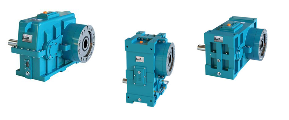
When you compare two extruder gearboxes of identical design, identical gear ratio, and identical rated torque, the difference in their real-world performance, service life, and reliability often comes down to one thing: the materials from which they are made. A gearbox manufactured from the correct grades of alloy steel, precision-cast iron, engineering-grade bearing steel, and appropriate sealing elastomers will reliably serve a continuous extrusion line for fifteen to twenty years. One manufactured from inferior materials — even if the design appears identical on paper — may begin showing signs of premature wear, seal failure, or housing deflection within a fraction of that time. Material selection in extruder gearbox design is not a single decision — it is a cascade of interconnected choices, each made for specific engineering reasons that directly affect performance. The gear teeth must resist surface pitting and root bending fatigue under sustained high contact stresses. The housing must maintain dimensional accuracy under load across the operating temperature range. The bearings must carry both radial and axial loads for tens of thousands of operating hours. The seals must exclude abrasive plastic dust while retaining oil under elevated temperatures. The lubricant must maintain adequate viscosity and film thickness at the operating temperature while resisting oxidation and contamination. This guide examines every major material category used in a high-performance extruder gearbox — gear materials, housing materials, shaft materials, bearing materials, seal materials, and lubrication — explaining what each material is, why it is selected over the alternatives, what properties make it suitable for extruder gearbox duty, and what the consequences are when inferior materials are used. By the end of this guide, you will be able to evaluate gearbox material specifications intelligently and ask the right questions when comparing suppliers.
Why Material Selection Matters in Extruder Gearboxes
The operating environment inside a plastic extruder gearbox places extreme and simultaneous demands on every material used in its construction. Understanding these demands is the starting point for understanding why material selection is so critical.
The Four Mechanical Stresses That Materials Must Withstand
- High Contact Stress at Gear Mesh: The contact pressure between meshing helical gear teeth in an extruder gearbox can reach 1,000 to 2,000 MPa — comparable to the pressure at the tip of a ballpoint pen over a tiny contact area. Gear materials must resist surface fatigue (pitting) and plastic deformation under these pressures for millions of contact cycles over the gearbox service life.
- Cyclic Bending Stress at Gear Tooth Root: Every time a gear tooth comes into mesh, it deflects under the transmitted load like a small cantilever beam. This cyclic bending stress, repeated at the gear meshing frequency, causes fatigue crack initiation at the tooth root over time. Gear materials must have high bending fatigue strength to resist this failure mode.
- Sustained High Torque on Shafts and Bearings: Shafts and bearings carry the combined effect of gear mesh forces — radial loads from the gear tooth tangential and separating forces, and axial loads from the helical gear thrust component and the extruder screw reaction force. These loads are sustained continuously, often for 20 or more hours per day.
- Thermal Cycling and Elevated Temperature: The gearbox starts cold and reaches operating temperature within 30 to 60 minutes. This thermal cycling creates differential expansion stresses between components of different materials and different wall thicknesses. At operating temperature, materials must retain their mechanical properties and dimensional stability.
The Cost of Wrong Material Choices
The consequences of inferior material selection manifest progressively. In the first year, a cheaper-material gearbox may perform identically to a premium-material unit. By year three, surface pitting on gear teeth becomes visible. By year five, the bearing races show accelerated fatigue, and oil contamination from metal particles becomes problematic. By year seven, major component replacement is required. By year ten, the gearbox needs full replacement. A premium-material gearbox in the same application, correctly maintained, would still be mid-service-life.
Material Quality — Its Impact on Service Life
Premium gear steel (18CrNiMo7-6, case-hardened, precision-ground): 15 – 25 year service life
Standard alloy steel (20MnCr5, adequate treatment): 10 – 18 year service life
Lower-grade steel (inadequate hardenability or surface treatment): 4 – 8 year service life
Poor-quality steel (incorrect grade, inadequate heat treatment): 2 – 5 year service life
The difference in material cost between premium and poor-quality gear steel is typically 15 – 30%.
The difference in total life-cycle cost can be 3x to 5x in favour of the premium material.
Gear Materials — The Heart of the Gearbox
The gears are the most mechanically critical components in any extruder gearbox. The material from which the gears are made, combined with the heat treatment and surface finishing processes applied to them, determines the gearbox’s torque capacity, its efficiency, its noise level, and ultimately its service life. There is no single decision in gearbox construction that has more impact on performance than the selection and treatment of the gear material.
The Required Properties of a Gear Material
For extruder gearbox duty, the gear material must satisfy several competing requirements simultaneously:
- High Surface Hardness: The gear tooth contact surfaces must be very hard — typically 58 to 64 HRC (Rockwell C hardness) — to resist pitting fatigue under the extreme contact pressures of gear mesh. Higher surface hardness allows higher contact stress capacity and longer surface fatigue life.
- High Core Toughness: Below the hard surface layer, the gear material must be tough and ductile to absorb shock loads and resist brittle fracture. A gear that is hard all the way through would be extremely brittle and would fracture catastrophically under shock loads.
- High Bending Fatigue Strength: The gear tooth root must resist the cyclic bending stresses of repeated loading through millions of mesh cycles without initiating a fatigue crack.
- Good Hardenability: The steel must respond consistently and predictably to the carburising and hardening heat treatment process, achieving the specified case depth and surface hardness without distortion that would require excessive grinding correction.
- Machinability Before Hardening: The steel must be machinable in the annealed condition to allow accurate hobbing of the gear tooth profile before heat treatment.
- Dimensional Stability After Hardening: Minimal distortion during heat treatment is essential to preserve the accuracy of the gear tooth geometry and to minimise the amount of grinding required to achieve the final tolerance.
The Primary Gear Steel Grades for Extruder Gearboxes
Case-hardening (carburising) alloy steels are the standard gear material for high-performance extruder gearboxes. These steels have a relatively low carbon content in the core (0.14% to 0.22% carbon), which provides the required core toughness, combined with sufficient alloying elements to achieve good hardenability and response to surface carbon enrichment (carburising).
| Steel Grade | Standard | Key Alloying Elements | Surface Hardness (HRC) | Typical Application in Gearbox |
| 18CrNiMo7-6 | EN 10084 | Cr 1.5–1.8%, Ni 1.4–1.7%, Mo 0.25–0.35% | 60–64 HRC | Premium input and intermediate stage gears — demanding applications |
| 16MnCr5 | EN 10084 | Mn 1.1–1.4%, Cr 0.8–1.1% | 58–62 HRC | Standard duty gears — widely used in medium-performance gearboxes |
| 20MnCr5 | EN 10084 | Mn 1.1–1.4%, Cr 1.0–1.3% | 58–63 HRC | Good all-round gear steel — common in quality extruder gearboxes |
| 15CrNi6 | EN 10084 | Cr 1.4–1.7%, Ni 1.4–1.7% | 60–64 HRC | High-toughness gears for shock-load applications |
| 17CrNiMo6 | EN 10084 | Cr 1.5%, Ni 1.5%, Mo 0.3% | 60–64 HRC | Premium grade — high contact fatigue strength for heavy duty |
| 42CrMo4 | EN 10083 | Cr 0.9–1.2%, Mo 0.15–0.30% | 54–58 HRC | Through-hardened (not case-hardened) — used where case hardening is impractical |
Among these grades, 18CrNiMo7-6 is widely regarded as the premium standard for high-performance extruder gearbox gears. Its combination of chromium, nickel, and molybdenum alloying gives it outstanding hardenability — the ability to achieve the specified case depth and surface hardness consistently throughout the full gear blank cross-section — along with high core toughness that resists shock loads. The nickel content specifically enhances low-temperature toughness and fatigue crack resistance at the case-core transition zone.
Why Alloy Steel Composition Matters — The Role of Each Element
| Alloying Element | Primary Effect on Steel Properties | Why It Matters in Extruder Gearbox Gears |
| Carbon (C) | Provides base hardness after quenching; controls core toughness | Low core carbon (0.14–0.22%) ensures tough core; carburised surface carbon (0.7–0.8%) gives hard case |
| Chromium (Cr) | Increases hardenability and wear resistance; forms hard carbides | Essential for achieving full case hardness across large gear cross-sections |
| Nickel (Ni) | Increases core toughness and fatigue crack resistance | Critical for shock load resistance and resistance to fatigue crack propagation at tooth root |
| Molybdenum (Mo) | Increases hardenability; prevents temper brittleness | Ensures consistent properties through full heat treatment cycle; prevents embrittlement |
| Manganese (Mn) | Increases strength and hardenability; improves machinability | Cost-effective hardenability enhancer; present in most gear steels |
| Phosphorus (P) | Impurity — must be minimised (max 0.025%) | Causes temper brittleness and reduces toughness; premium steels have tight P limits |
| Sulphur (S) | Impurity at high levels; improves machinability at low levels | Must be controlled (max 0.035%); excess causes hot shortness and reduces fatigue strength |
Gear Manufacturing and Surface Treatment
Even the best gear steel will not achieve its potential performance without the correct manufacturing and heat treatment processes. The transformation of a gear steel blank into a finished, precision-ground gear tooth is a multi-stage process, and the quality of each stage directly affects the final gear’s contact fatigue strength, bending fatigue strength, and dimensional accuracy.
Stage 1 — Gear Blank Forging
The manufacturing process begins with forging the gear blank from bar stock or billet. Forging refines the steel grain structure and ensures that the metal flow lines (fibre structure) are oriented favourably relative to the gear tooth geometry. A forged gear blank has significantly better toughness and fatigue resistance than one machined from as-rolled bar, because the forging process aligns the grain structure with the tooth profile rather than cutting across it.
In high-performance extruder gearbox manufacture, all gear blanks above a certain size threshold are specified as forgings — not machined directly from bar stock. This requirement is often the first distinguishing factor between a premium gearbox and a standard-grade unit.
Stage 2 — Rough Machining and Hobbing
The forged blank is rough-machined to near-net dimensions, then the gear teeth are cut by a hobbing machine — a precision gear-cutting process using a rotating multi-tooth hob cutter that generates the involute tooth profile. After hobbing, the gear teeth are in their near-final geometric form but with a relatively coarse surface finish and residual machining stresses.
Stage 3 — Case Carburising
Case carburising is the critical heat treatment process that gives the gear teeth their hard surface layer. The machined gear blank is heated to approximately 900 to 950 degrees Celsius in a controlled atmosphere furnace containing a carbon-rich gas (methane or propane). Over a carefully controlled time period, carbon diffuses into the surface of the steel to a depth of 0.8 to 2.0 mm — the case depth — raising the surface carbon content from approximately 0.18% (core) to 0.7 to 0.9% (case). This carbon-enriched surface layer is then capable of being hardened to 60 to 64 HRC by quenching.
Case Carburising — Key Process Parameters
Carburising temperature: 900 – 950°C (in controlled atmosphere furnace)
Case depth (effective): 0.8 – 1.5 mm for standard extruder gears 1.2 – 2.0 mm for large or heavily loaded gears
Surface carbon content: 0.70 – 0.85% after carburising
Core carbon content: 0.14 – 0.22% (unchanged)
Surface hardness achieved: 58 – 64 HRC after quenching
Core hardness (typical): 30 – 40 HRC (tough and ductile)
Stage 4 — Hardening and Tempering
After carburising, the gear is quenched — rapidly cooled in oil or a controlled-atmosphere quench — to lock in the hard martensitic microstructure at the carburised surface while the core transforms to a tougher microstructure. The gear is then tempered at 150 to 200 degrees Celsius to relieve quenching stresses and reduce the risk of grinding cracks during subsequent precision grinding.
Stage 5 — Precision Gear Grinding
After heat treatment, the gear teeth are precision-ground on a CNC gear grinding machine to remove heat treatment distortion and achieve the final tooth profile accuracy. This is the most technologically demanding stage of gear manufacture, and the quality of the grinding operation determines the final gear quality class, which in turn determines the noise level, efficiency, and load distribution of the gear pair.
| DIN Quality Class | Profile Tolerance | Typical Application | Effect on Gearbox Performance |
| Class 4 | ±2 – 3 µm | Aerospace / precision instruments | Exceptionally quiet; maximum efficiency |
| Class 5 | ±3 – 5 µm | High-performance industrial gearboxes | Very quiet; excellent load distribution; premium extruder gearboxes |
| Class 6 | ±5 – 8 µm | Standard quality industrial gearboxes | Good noise level; adequate for most extrusion applications |
| Class 7 | ±8 – 12 µm | General industrial gearboxes | Acceptable noise; some vibration; adequate for light-duty extrusion |
| Class 8–10 | ±12 – 25 µm | Low-cost / commodity gearboxes | Elevated noise and vibration; poorer load distribution; shorter service life |
High-performance extruder gearboxes should be manufactured to DIN quality class 5 or better. A gearbox manufactured to class 7 or lower may initially appear to operate acceptably, but the poorer load distribution across the tooth face width — caused by less accurate tooth geometry — concentrates the contact stress at specific zones, accelerating pitting initiation and ultimately reducing the gear service life significantly.
Stage 6 — Optional Surface Enhancement Treatments
Some premium extruder gearbox manufacturers apply additional surface enhancement treatments to further improve gear performance beyond what case hardening and precision grinding alone can achieve:
- Shot Peening: The gear tooth root is bombarded with hardened steel shot at high velocity, plastically deforming the surface layer and inducing compressive residual stresses. These compressive stresses at the tooth root significantly increase the bending fatigue limit — the stress level below which fatigue cracks will not initiate — extending gear life under repeated loading cycles.
- Phosphate Coating: A thin manganese or zinc phosphate coating is applied to gear tooth flanks before the gearbox is assembled. This porous coating retains lubricating oil at the gear surface during the critical running-in period, reducing the risk of adhesive wear (scuffing) on first load application.
- Superfinishing (Isotropic Finishing): A chemomechanical finishing process that removes the microscopic peaks from the ground tooth surface, producing a near-mirror finish with surface roughness below Ra 0.1 µm. This reduces gear mesh friction, lowers operating temperature, and can improve efficiency by 0.5 to 1.5% per gear stage.
Shaft Materials — Input, Intermediate, and Output Shafts
The shafts of an extruder gearbox are the structural backbone of the power transmission system. They must transmit the full torque from stage to stage while simultaneously carrying the bending loads from gear mesh forces and, in the case of the output shaft, the very high axial thrust load from the extruder screw.
Shaft Material Requirements
Extruder gearbox shafts are manufactured from medium-carbon alloy steels that are through-hardened and tempered to achieve high tensile strength, good fatigue resistance, and adequate toughness. Unlike the gears, which use case-hardening steels to achieve a hard surface over a tough core, the shafts use through-hardening steels that develop their mechanical properties uniformly through the full cross-section.
| Steel Grade | Tensile Strength (MPa) | Key Properties | Application in Gearbox | Typical Heat Treatment |
| 42CrMo4 | 900 – 1,100 MPa | High strength, good toughness, good machinability | Input and intermediate shafts — standard duty | Quench and temper to 280–320 HB |
| 34CrNiMo6 | 1,000 – 1,200 MPa | Higher strength, excellent toughness, Ni toughening | Output shaft — high torque applications | Quench and temper to 300–340 HB |
| 30CrNiMo8 | 1,100 – 1,300 MPa | Maximum strength grade, very high toughness | Output shaft — heavy duty / shock load | Quench and temper to 310–360 HB |
| 36CrNiMo4 | 900 – 1,100 MPa | Good combination of strength and toughness | General shaft duty — good balance of properties | Quench and temper to 280–330 HB |
Output Shaft — Special Material Considerations
The output shaft deserves particular attention because it operates under the most demanding loading conditions in the gearbox. It must simultaneously transmit the maximum output torque (torsional shear stress), carry the large bending moment from the output gear mesh force (bending stress), and react against the very high axial thrust force from the extruder screw (compressive axial stress at the thrust bearing seat). This combination of three simultaneous stress states makes the output shaft the most highly stressed shaft in the gearbox.
For this reason, quality extruder gearbox manufacturers specify the highest strength grade available for output shafts — typically 34CrNiMo6 or 30CrNiMo8 — rather than the same grade used for less-loaded intermediate shafts. The coupling journal at the output end is typically induction-hardened to achieve a surface hardness of 52 to 58 HRC, increasing wear resistance at the coupling interface and improving fatigue resistance at this high-stress location.
Gearbox Housing Materials — Cast Iron vs Fabricated Steel
The gearbox housing serves multiple critical functions simultaneously: it maintains the geometric alignment of all shafts and gears under load; it contains the lubrication oil; it provides the structural foundation for the complete drive system; and in many designs it contributes significantly to heat dissipation from the operating gearbox. The housing material must satisfy all of these requirements reliably across the full temperature range and load range of continuous extrusion duty.
Grey Cast Iron — GG25 (EN-GJL-250)
Grey cast iron is the most widely used housing material for medium to large extruder gearboxes. It offers an excellent combination of properties that are particularly well-suited to gearbox housing duty:
- Excellent Castability: Grey iron can be cast into complex housing shapes with internal galleries, bearing pockets, oil sump formations, and cooling fin geometry in a single casting operation, without the need for extensive machining to create these features.
- Good Vibration Damping: The graphite flake microstructure of grey iron provides excellent vibration damping capacity — typically 3 to 10 times better than steel. This damping reduces the transmission of gear mesh vibration through the housing to the extruder frame and reduces noise levels.
- High Rigidity (High Stiffness-to-Cost Ratio): Grey iron has high compressive strength and stiffness, maintaining bearing bore alignment under gear mesh loads without excessive deflection.
- Good Thermal Conductivity: Effective heat dissipation from the gearbox oil to the housing surface and then to the surrounding air, aided by the ability to cast cooling fins integrally into the housing.
- Excellent Machinability: Grey iron machines easily to tight tolerances, allowing bearing bore accuracy to within a few micrometres — the precision needed for correct shaft alignment.
Grey Cast Iron GG25 — Key Properties
Tensile strength: 250 MPa (minimum)
Compressive strength: 600 – 800 MPa
Hardness: 180 – 230 HB
Thermal conductivity: 50 W/m·K
Vibration damping capacity: High (3 – 10x steel)
Density: 7.2 g/cm³
Typical wall thickness in gearbox housing: 15 – 25 mm
Ductile (Nodular) Cast Iron — GGG50 (EN-GJS-500-7)
Ductile iron, also known as nodular or spheroidal graphite iron, is used in gearbox housings for applications where higher impact resistance and tensile strength are required than grey iron provides. The modification of the graphite structure from flakes (grey iron) to spheroids (ductile iron) dramatically improves tensile strength and ductility while retaining the excellent castability and machinability of cast iron.
Ductile iron GGG50 is preferred for extruder gearbox housings in applications with significant shock loads — such as machines that experience frequent cold starts with rigid PVC or highly filled materials — where the cyclic overload stresses during startup could risk cracking a grey iron housing over time. The higher tensile strength (500 MPa minimum) and elongation (7% minimum) of GGG50 provide a substantially greater safety margin against housing fracture under these conditions.
Fabricated Steel Housing
For very large extruder gearboxes — typically those with output torque ratings above 100,000 Nm where large casting patterns become impractical or uneconomical — the housing is fabricated from welded structural steel plate and section. The fabricated housing is stress-relieved after welding, then precision-machined for all bearing bores and mating faces. Fabricated steel housings offer:
- Greater Tensile and Impact Strength: Structural steel offers much higher tensile strength and ductility than any cast iron grade, making fabricated housings appropriate for the highest torque and highest shock load applications.
- Flexibility for Non-Standard Geometries: Fabricated housings can be designed and built to any geometry without the need for casting patterns — particularly useful for custom or one-off large gearbox designs.
- Reduced Vibration Damping: The main disadvantage of fabricated steel housing is its lower inherent vibration damping compared to cast iron. Some fabricated gearboxes incorporate damping inserts or are mounted on vibration-isolating pads to compensate for this.
Bearing Materials — Rolling Elements and Races
Rolling element bearings are among the most precision-engineered components in any mechanical system. In a high-performance extruder gearbox, the bearings must sustain very high radial loads from gear mesh forces, precise shaft alignment across all operating speeds and temperatures, and in the case of the output shaft bearings, very high axial loads from the extruder screw thrust. The materials used in bearing manufacture directly determine the bearing’s load capacity, fatigue life, and operating temperature range.
Rolling Element and Race Material — Through-Hardening Bearing Steel
The overwhelming standard material for extruder gearbox bearing rolling elements (balls, cylinders, tapered rollers) and bearing inner and outer races is 100Cr6 — a high-carbon, chromium-alloyed through-hardening steel that has been the global standard bearing steel for over a century. When through-hardened to 60 to 66 HRC, 100Cr6 achieves an outstanding combination of surface fatigue resistance, high compressive strength, and dimensional stability that makes it ideal for the high Hertzian contact stresses in rolling element bearings.
Carbon content: 0.93 – 1.05% (high carbon — ensures deep hardenability)
Chromium content: 1.35 – 1.65% (forms hard chromium carbides)
Through-hardness: 60 – 66 HRC after hardening
Surface finish: Ra 0.025 – 0.05 µm on bearing races (mirror finish)
Dimensional stability: Excellent — sub-micrometre dimensional control
Operating temp limit: 120°C continuous (standard), 150°C (stabilised grade)
Vacuum degassed: Premium bearings use vacuum-arc remelted (VAR) steel for minimal inclusion content and maximum fatigue life
Why Bearing Steel Quality Matters in Extrusion Applications
The fatigue life of a rolling element bearing is extremely sensitive to the cleanliness (freedom from non-metallic inclusions) of the bearing steel. Non-metallic inclusions — oxide particles, sulphide stringers, and other impurities that are present in lower-quality steels — act as stress concentration sites within the bearing material. Under the cyclic contact stresses of bearing operation, cracks initiate at these inclusion sites and propagate to cause subsurface fatigue spalling (flaking off of the bearing surface).
Premium bearing manufacturers specify bearing steel that has been vacuum-arc remelted (VAR) or electroslag remelted (ESR) to remove inclusions and achieve exceptional steel cleanliness. Bearings made from VAR or ESR steel have demonstrably longer fatigue life than those made from standard electric arc furnace steel — often by a factor of 2 to 5 times under equivalent loading conditions. For extruder gearboxes designed for 20,000 to 50,000 operating hour bearing life, the use of premium-quality bearing steel is not a luxury — it is an engineering necessity.
Cage Materials in Extruder Gearbox Bearings
The cage (retainer) that spaces the rolling elements within a bearing and guides them around the race is made from a different material than the races and rolling elements. Common cage materials in extruder gearbox bearings include:
- Pressed Steel Cage: Formed from sheet steel and riveted or welded. Low cost, adequate for standard duty. Used in lower-cost extruder gearboxes.
- Machined Brass Cage: Precision-machined from high-tensile brass or bronze. Excellent sliding properties against the steel rolling elements, good oil retention in the cage pockets, and high resistance to centrifugal forces at high speeds. Used in premium extruder gearboxes for input and intermediate shaft bearings at higher speeds.
- Glass-Fibre Reinforced Polyamide (PA66-GF) Cage: Lightweight, low-friction polymer cage used in medium-speed bearings. Good oil compatibility and dimensional stability. Becoming increasingly common in quality industrial bearings as a cost-effective alternative to brass for moderate-speed applications.
- Machined Steel Cage: Precision-machined solid steel cage for heavy-duty, very high-load applications such as the thrust bearing assembly in large extruder gearboxes. Maximum strength and dimensional stability.
Thrust Bearing Materials — The Axial Load Specialists
The thrust bearing assembly in an extruder gearbox is the most mechanically demanding bearing application in the entire gearbox — and arguably in any standard industrial gearbox design. It must sustain the full axial thrust force generated by the extruder screw (which can reach hundreds of kilonewtons in large extruders) continuously and indefinitely, without perceptible axial shaft movement and without degradation in load-carrying capacity over the gearbox service life.
Spherical Roller Thrust Bearings
The most common thrust bearing type in medium to large extruder gearboxes is the spherical roller thrust bearing. This bearing has barrel-shaped rolling elements that run on a spherical raceway surface, allowing it to accommodate minor shaft misalignment while carrying both axial and radial loads simultaneously.
The rolling elements and races in spherical roller thrust bearings are manufactured from 100Cr6 or, for the most demanding applications, from stainless bearing steel (X65Cr14 or X45Cr13) that provides additional corrosion resistance in environments where condensation or process moisture may be present. The rolling element geometry is precision-ground to tolerances measured in micrometres, ensuring that the axial load is distributed as uniformly as possible across all rolling elements.
Tapered Roller Bearing Pairs for Thrust Applications
In smaller extruder gearboxes and in applications where the thrust bearing must fit within a compact axial space, paired tapered roller bearings arranged in back-to-back (DB) or face-to-face (DF) configuration are used for thrust absorption. The tapered roller geometry allows these bearings to carry both axial and radial loads, with the load-sharing ratio between axial and radial determined by the contact angle of the taper.
For extruder thrust applications, back-to-back (DB) mounting is preferred because it provides a wide, stable support base for the shaft, minimising shaft deflection under the combined axial and bending loads of the output shaft. The bearing pairs are carefully pre-loaded during assembly to eliminate internal clearance and prevent roller skewing under the predominantly axial loads of extrusion operation.
Seal Materials — Keeping Oil In and Contaminants Out
The shaft sealing system of an extruder gearbox operates in one of the most challenging environments faced by any industrial seal: the plastic extrusion plant floor, where the air is laden with polymer dust, glass fibre fragments, calcium carbonate particles, or other abrasive materials depending on the process. At the same time, the seals must retain lubricating oil under the centrifugal action of a rotating shaft at elevated temperature over long continuous operating periods.
Primary Seal Elastomer Materials
| Seal Material | Abbreviation | Temp Range | Key Properties | Recommendation for Extrusion |
| Nitrile Rubber | NBR | -40 to +100°C | Good oil resistance; cost-effective | Acceptable for standard temperature applications |
| Hydrogenated Nitrile | HNBR | -30 to +150°C | Superior heat and oil resistance vs NBR | Good choice for moderate-high temperature gearboxes |
| Fluoroelastomer | FKM | -20 to +200°C | Excellent oil, heat and chemical resistance; long service life | Recommended for all extruder gearbox applications |
| Polytetrafluoroethylene | PTFE | -60 to +260°C | Lowest friction of all seal materials; excellent chemical resist. | Ideal for high-speed input shafts or high-temp environments |
| Silicone Rubber | VMQ | -60 to +180°C | Excellent temperature range; lower mechanical strength | Suitable for low-load seal applications at extreme temperatures |
| Polyacrylate | ACM | -25 to +175°C | Good heat and oil resistance; moderate performance | Acceptable but FKM generally preferred for extrusion duty |
Fluoroelastomer (FKM, commercially known as Viton) is the preferred seal material for high-performance extruder gearbox shaft seals. Its exceptional resistance to heat (up to 200 degrees Celsius continuous), excellent compatibility with all mineral and synthetic gear oils, and superior resistance to chemical degradation from oil additive packages give it a service life several times that of standard NBR seals in the elevated-temperature, oil-immersed environment of an extruder gearbox.
Seal Housing and Spring Materials
The metal casing of a radial lip seal is typically manufactured from low-carbon steel (DC01 or equivalent), pressed and deep-drawn to form the outer shell and inner reinforcing ring. The garter spring that maintains the lip contact force is manufactured from corrosion-resistant spring steel wire — either 302/304 stainless steel or carbon spring steel with an anticorrosion coating. The spring material must maintain its spring force over the full operating temperature range without relaxation (stress relaxation at elevated temperature is a known failure mode for standard carbon steel springs in hot seals).
Secondary Sealing and Dust Exclusion Materials
As discussed in our gearbox design guide, high-performance extruder gearboxes use a multi-stage sealing arrangement at the output shaft. The secondary seal or dust excluder — the element positioned outboard of the primary FKM lip seal — is typically manufactured from either:
- Polyurethane (PU) V-ring: An extremely flexible, lip-type seal that fits on the shaft and seals against a counterface on the housing. Polyurethane offers excellent abrasion resistance against plastic dust and glass fibre particles, making it ideal as a secondary exclusion element in the abrasive extrusion environment.
- PTFE Labyrinth Elements: PTFE (polytetrafluoroethylene) is used for machined labyrinth seal inserts in premium gearboxes. Its extremely low friction coefficient (0.04) prevents heat generation at the labyrinth interface, and its chemical inertness makes it impervious to attack by any polymer dust or process chemicals.
Lubrication — The Liquid Material That Enables Everything
Lubrication oil is arguably the most important material in any gearbox — not because it is the most structurally significant, but because the performance and service life of every other material in the gearbox depends entirely on it doing its job correctly. Without an adequate, clean, correctly viscous lubricant film between every pair of moving surfaces, even the best gear steel, bearing steel, and housing material will fail rapidly.
Mineral Base Oil vs Synthetic Base Oil
| Oil Type | Mineral Gear Oil (Group I/II) | Synthetic PAO Gear Oil (Group IV) |
| Base stock origin | Refined from crude petroleum | Synthesised from polyalphaolefin (PAO) monomers |
| Viscosity index (VI) | 90 – 110 (varies with temp) | 140 – 170 (very stable with temp) |
| Oxidation stability | Moderate — oxidises at > 70°C | Excellent — stable at 90–100°C continuous |
| Oil change interval | 3,000 – 5,000 hours | 8,000 – 12,000 hours |
| Low temperature performance | Acceptable — may be stiff below 5°C | Excellent — flows freely from -30°C |
| Film strength at high temp | Decreases significantly above 70°C | Maintains better film at 80–100°C |
| Gear mesh efficiency | Good | Slightly better — lower traction coefficient |
| Cost (relative) | Low to moderate | 3 – 6x cost of mineral oil |
| Recommended for | Standard duty; moderate ambient temp | Continuous duty; high ambient; hot gearboxes |
Extreme Pressure (EP) Additive Packages
Regardless of whether mineral or synthetic base oil is used, extruder gearbox lubricants contain an extreme pressure (EP) additive package. EP additives are chemical compounds — typically organo-sulphur, organo-phosphorus, or borate-based compounds — that react with metal surfaces under the very high contact pressures and temperatures of gear tooth mesh to form a protective surface layer. This layer prevents metal-to-metal welding (scuffing) under momentary high-load conditions such as startup or process shock loads.
The EP additive formulation must be carefully selected for compatibility with the bearing materials in the gearbox. Some aggressive EP additive packages containing active sulphur compounds can attack the silver or copper components in certain bearing designs (particularly copper-alloy bearing cages) or can cause corrosion of bronze components if present. Always use an EP gear oil specifically approved by the gearbox manufacturer for use with that gearbox’s internal materials.
ISO Viscosity Grade Selection for Extruder Gearboxes
| Application / Operating Condition | Ambient Temperature | Recommended Viscosity Grade | Oil Type |
| Small / high-speed gearbox | 15 – 35°C | ISO VG 150 | Mineral EP or PAO |
| Medium gearbox — standard ambient | 20 – 40°C | ISO VG 220 | Mineral EP or PAO |
| Medium-large gearbox — standard | 25 – 45°C | ISO VG 320 | Mineral EP or PAO |
| Large gearbox — warm ambient | 35 – 55°C | ISO VG 320 or 460 | PAO synthetic preferred |
| Very large / heavy duty — hot ambient | 40 – 60°C | ISO VG 460 | PAO synthetic — strongly recommended |
| Tropical or very high ambient | 45 – 65°C | ISO VG 460 or 680 | PAO synthetic — essential |
Cooling System Materials
The cooling system materials in an extruder gearbox must handle hot lubricating oil on one side and cooling water on the other, without corrosion, fouling, or leakage, over many years of continuous service. The choice of materials for cooling coils and heat exchangers therefore has a direct impact on gearbox reliability.
Internal Cooling Coil Materials
Internal cooling coils — immersed in the oil sump — are typically manufactured from seamless copper or copper-alloy tube (CuNi10Fe or CuNi30Mn, phosphorus-deoxidised copper to EN 12449). Copper alloys are preferred for cooling coils because of their excellent thermal conductivity (approximately 400 W/m·K for pure copper, 50 to 200 W/m·K for copper-nickel alloys), which maximises the heat transfer rate from the oil to the cooling water. However, copper and copper-alloys can be attacked by certain EP additive packages containing active sulphur compounds — this is why the oil specification must always be checked for compatibility with the cooling coil material.
For gearboxes used in aggressive chemical environments where copper attack is a concern, stainless steel cooling coils (304 or 316 stainless, seamless tube to EN 10216-5) are used as an alternative. Stainless steel has lower thermal conductivity than copper but is completely resistant to sulphur-containing EP additive attack and is unaffected by all standard gear oil formulations.
External Heat Exchanger Materials
External shell-and-tube or plate heat exchangers for gearbox oil cooling are typically constructed with carbon steel or stainless steel shells and headers, with the heat transfer tubes made from either copper-nickel alloy (for standard cooling water), admiralty brass (for mildly corrosive water), or stainless steel (for aggressive or high-chloride cooling water). The gaskets and O-rings that seal the plate heat exchanger are selected from nitrile or EPDM rubber for standard temperatures and fluoroelastomer for higher-temperature applications.
Fasteners, Keys, and Coupling Materials
While fasteners, keys, and couplings are smaller components, their material selection has a direct impact on gearbox integrity and reliability — particularly under the high torque, vibration, and thermal cycling of continuous extrusion operation.
- Housing Bolts and Studs: Grade 10.9 or 12.9 alloy steel fasteners are used for all structural housing connections in premium extruder gearboxes. These grades provide tensile strengths of 1,040 MPa and 1,220 MPa respectively, ensuring that housing joints remain adequately pre-loaded against operating forces and thermal expansion cycles. Zinc or nickel plating is applied for corrosion resistance in the moist extrusion environment.
- Parallel Keys and Woodruff Keys: Shaft-to-gear and shaft-to-coupling key connections are made from high-tensile alloy steel keys — typically Grade C45 through-hardened to 45 to 55 HRC — that resist shear failure under the transmitted torque and fretting wear at the keyway contact faces.
- Flexible Coupling Elements: The flexible element in the motor-to-gearbox coupling — which absorbs misalignment and vibration between the motor and gearbox — is typically manufactured from polyurethane (PU), natural rubber, or neoprene, depending on the required hardness, temperature range, and torque rating. PU elements are preferred for their combination of high torque capacity, good oil resistance, and long fatigue life.
- Breather Assembly Materials: The breather filter element is manufactured from sintered bronze, stainless steel mesh, or glass fibre filtration media, selected to allow air flow while preventing ingress of particles above a specified size (typically 25 to 50 micrometres). The breather housing is typically aluminium or zinc-die-cast steel for lightweight, corrosion-resistant enclosure.
Material Quality Standards and Certifications
For engineers and procurement professionals evaluating extruder gearbox quality, the material standards and certifications against which components are manufactured provide an objective framework for comparison. The following standards and certifications are relevant to extruder gearbox materials:
| Standard / Certification | Applies To | What It Specifies / Why It Matters |
| EN 10084 | Case-hardening gear steels | Defines chemical composition, mechanical properties, and testing requirements for all standard case-hardening steels including 18CrNiMo7-6, 16MnCr5, 20MnCr5 |
| EN 10083 | Through-hardening alloy steels | Applies to shaft steels — 42CrMo4, 34CrNiMo6 etc. Specifies composition and mechanical properties for each grade |
| DIN 3960 / ISO 1328 | Gear accuracy grades | Defines gear quality classes (1 to 12) based on profile, lead, pitch, and runout tolerances. Classes 4 to 6 are appropriate for high-performance extruder gearboxes |
| ISO 281 | Bearing life calculation | Standard method for calculating L10h bearing life. Allows comparison of bearing sizing adequacy across different gearbox designs |
| EN-GJL-250 / EN-GJS-500-7 | Cast iron housing grades | European standard for grey iron and ductile iron grades. Specifies tensile strength, hardness, and composition for housing castings |
| ISO VG (ASTM D445) | Lubricant viscosity grades | International standard for classifying gear oil viscosity grades. Ensures consistent viscosity specification across oil brands and suppliers |
| ISO 4406 | Oil cleanliness / particle count | Defines cleanliness codes for hydraulic and lubrication fluids. Monitoring oil to ISO 4406 gives early warning of contamination or internal wear |
| EN 12449 | Copper alloy tube (cooling coils) | Specifies dimensions, tolerances, and material properties for seamless copper and copper-alloy tube used in cooling coils |
How to Identify Inferior Materials in a Gearbox
When comparing extruder gearboxes from different suppliers, the following indicators can help identify whether premium or inferior materials have been used — even without access to material certificates or metallurgical testing:
- Ask for the Gear Steel Grade and Heat Treatment Specification: A quality manufacturer will readily provide the gear steel grade (e.g. 18CrNiMo7-6), case depth specification, and surface hardness requirement. Evasive or vague answers on these parameters suggest lower-grade materials.
- Ask for the DIN Gear Quality Class: A premium extruder gearbox should be manufactured to DIN class 5 or 6. If the manufacturer cannot state the quality class, the gears are unlikely to have been precision-ground to a defined quality standard.
- Check the Housing Weight: A quality cast iron housing for a given torque rating will have a specific minimum weight determined by the required wall thickness and structural geometry. A suspiciously light housing for its rated torque suggests thin walls that may deflect under load, compromising gear alignment.
- Inspect the Gear Tooth Surface Finish: On a new gearbox with inspection covers removed, premium case-hardened and precision-ground gear teeth should have a uniform, slightly reflective silver-grey ground finish. Rough, dull, or visibly machined (non-ground) tooth surfaces indicate hobbed-only gears without precision grinding — a significant quality reduction.
- Check the Seal Material Specification: Ask specifically whether the shaft seals are NBR or FKM (Viton). NBR seals have a significantly shorter service life in hot gearboxes. A quality supplier for extrusion applications will specify FKM seals as standard or as an available option.
- Request Material Certificates for Traceability: ISO 9001-certified gearbox manufacturers maintain material traceability records that link each component to its material certificate, heat treatment batch record, and dimensional inspection report. The ability to provide these records on request is itself an indicator of manufacturing quality.
Red Flags That Suggest Inferior Gearbox Materials
Manufacturer cannot state the gear steel grade by name (e.g. 18CrNiMo7-6 or 20MnCr5)
DIN gear quality class is class 7 or worse — or cannot be stated
Shaft seals are standard NBR rather than FKM for a hot-running application
Gearbox weight is significantly lower than competitive units at the same torque rating
No material certificates or heat treatment records available on request
Unusually low purchase price compared to established manufacturers (often reflects material downgrading)
Our Material Standards for Extruder Gearboxes
Every extruder gearbox we supply is built to defined and verifiable material standards — not to minimise cost, but to deliver the service life, efficiency, and reliability that continuous plastic extrusion duty demands. The material choices described throughout this guide are not aspirational — they are the actual specification standards applied to every gearbox that leaves our manufacturing facility.
Our Material Specification Summary
- Gear Steel: 18CrNiMo7-6 or 20MnCr5 alloy steel, forged blanks for all gears above 100 mm diameter, case carburised to 1.0 to 1.6 mm effective case depth, through-hardened to 60 to 63 HRC surface hardness, precision-ground to DIN class 5 after heat treatment.
- Gear Shot Peening: Applied as standard to all output stage gear tooth roots on gearboxes above 5,000 Nm rated torque, increasing the bending fatigue limit and extending tooth root service life.
- Output Shaft: 34CrNiMo6 alloy steel, quenched and tempered to minimum 1,000 MPa tensile strength, with induction-hardened coupling journal (52 to 56 HRC).
- Gearbox Housing: GGG50 ductile iron for standard extruder duty; GG25 grey iron where vibration damping is prioritised; fabricated steel for custom large units above 150,000 Nm. All bearing bores line-bored after assembly.
- Bearings: ISO-rated rolling element bearings from Tier 1 manufacturers, with brass or machined steel cages on thrust and output bearings; L10h design life minimum 25,000 hours.
- Shaft Seals: FKM (Viton) primary lip seals as standard for all applications; polyurethane V-ring secondary seal on output shaft as standard for plastic extrusion environments.
- Lubrication: ISO VG 320 mineral EP gear oil for standard applications; ISO VG 460 synthetic PAO on request for high-ambient or continuous-duty demanding environments.
- Cooling Coils: Seamless copper-nickel (CuNi10Fe) tube as standard; 316 stainless steel available for aggressive environments.
- Traceability: Full material certificates, heat treatment records, and dimensional inspection reports available for all structural components on request.
If you are evaluating a gearbox purchase and want to compare material specifications in detail, our technical team will provide a complete material specification sheet and answer any questions about how our materials compare to alternatives in the market.
Frequently Asked Questions (FAQs)
Q1. Why is 18CrNiMo7-6 considered the premium gear steel for extruder gearboxes?
18CrNiMo7-6 is regarded as the premium case-hardening gear steel for heavy-duty applications because of its unique combination of three alloying elements — chromium, nickel, and molybdenum — working together to provide properties that no single-element or two-element alloy can match. The chromium provides hardenability and wear resistance. The nickel increases toughness and fatigue crack resistance at the case-core transition zone, which is critical for preventing subsurface fatigue initiation under high contact stresses. The molybdenum ensures full hardenability through large cross-sections and prevents temper brittleness during the post-quench tempering cycle. Together, these elements give 18CrNiMo7-6 the highest contact fatigue strength and bending fatigue strength of any standard carburising steel in the EN 10084 series, making it the specification of choice for the most demanding gear applications.
Q2. Does the housing material affect the noise level of the gearbox?
Yes — the housing material has a measurable effect on the external noise level of a gearbox, primarily through its vibration damping characteristics. Grey cast iron has vibration damping capacity approximately 3 to 10 times higher than carbon steel of the same thickness, due to the energy-absorbing effect of the graphite flake microstructure. This means that a grey iron housing attenuates the gear mesh vibration frequencies more effectively than a steel housing before they reach the external surface and radiate as noise. In practice, a grey iron housing gearbox of a given gear quality class will typically measure 2 to 5 dB(A) quieter than an identical gearbox in a fabricated steel housing under equivalent operating conditions.
Q3. Can I change from mineral oil to synthetic PAO in my existing extruder gearbox?
In most cases, yes — PAO synthetic gear oil is miscible with mineral gear oil and can be used as a direct replacement at the same viscosity grade. However, before making the change, confirm three things: first, that all seal materials in the gearbox (particularly shaft seal O-rings and gaskets) are compatible with PAO oil — most modern FKM and NBR elastomers are, but some older polyacrylate seals may swell; second, that the cooling coil material is not silver-brazed copper (PAO can dissolve some silver brazing alloys in certain formulations); and third, drain the gearbox thoroughly and flush with a small quantity of the new PAO oil before filling to the correct level, to avoid contamination of the premium synthetic oil with degraded mineral oil residues.
Q4. What is the minimum acceptable DIN gear quality class for a continuous extrusion application?
For a continuous-duty plastic extrusion application, DIN class 6 should be considered the practical minimum, and class 5 is strongly recommended for demanding applications involving high viscosity materials, high gear ratios, or long planned service intervals. Class 7 and below will function but will produce more noise and vibration, have poorer load distribution across the tooth face width, and have reduced service life compared to class 5 to 6 gears under identical loading conditions. For twin screw compounding gearboxes and for counter-rotating PVC extruder gearboxes — where the combination of very high torque and continuous operation is most demanding — class 5 precision-ground gears should be specified as a minimum.
Q5. How do I know if the gears in my existing extruder gearbox are still in acceptable condition?
The most practical non-destructive indicators of gear condition in an operating gearbox are: the colour and particle content of the oil on the drain plug magnet (increased metallic particle accumulation indicates accelerating wear), the trend in gearbox operating noise (increasing noise level over months or years is characteristic of progressive gear tooth wear), the level of vibration measured on the housing using a vibration meter at the gear mesh frequency (increasing amplitude indicates tooth wear or damaged teeth), and the oil analysis results if periodic oil sampling is practised (rising iron content in ppm indicates gear or bearing wear rate). If any of these indicators show progressive deterioration, a borescope inspection through an inspection cover or an oil drain opening can provide a direct visual assessment of gear tooth surface condition without full gearbox disassembly.
Conclusion
The materials used in a high-performance extruder gearbox are not commodity choices — they are carefully engineered selections made at every level of the gearbox design to meet the specific and demanding requirements of continuous plastic extrusion duty. From the premium case-hardening alloy steel of the gear teeth to the fluoroelastomer lip seals at the shaft exits, from the precision-cast ductile iron housing to the vacuum-arc-remelted bearing steel of the thrust bearing races, every material in a quality extruder gearbox is there for a specific engineering reason.
Understanding these materials — what they are, why they are selected, and what distinguishes premium grades from standard grades — gives you the knowledge to evaluate gearbox quality beyond the catalogue specification sheet. A gearbox manufactured from 18CrNiMo7-6 gears precision-ground to DIN class 5, with FKM shaft seals, 34CrNiMo6 output shaft, GGG50 housing, and premium bearings with brass cages, is not just marginally better than one made from standard grades — it is fundamentally different in its capability to sustain continuous high-torque extrusion duty over a fifteen to twenty year service life without major intervention.
The price difference between a premium-material gearbox and a standard-material unit of equivalent rated torque is typically 20 to 40 percent at the time of purchase. The difference in total life-cycle cost — accounting for energy consumption, maintenance interventions, component replacements, and production downtime over a ten to fifteen year operating period — consistently favours the premium-material unit by a factor of two to three times. Material quality in an extruder gearbox is not a cost driver — it is a cost reducer. The investment in the right materials, at the point of specification, is the most effective single action available to reduce the long-term cost of your extrusion line’s drive system.
