
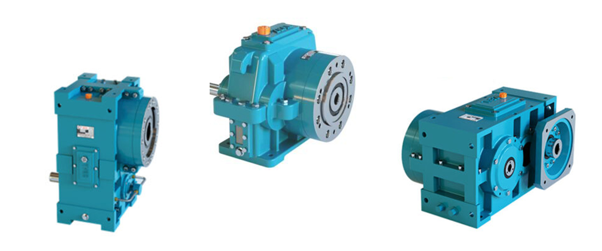
Every extruder gearbox sends warning signals before it fails — signals that, if recognised and acted upon promptly, allow maintenance to be planned and executed at a time and cost of your choosing rather than at the worst possible moment during a production run. The problem is that these signals are easy to miss when you are focused on production targets, shift handovers, and the hundred other daily demands of running a plastic processing plant. They start small — a slightly different sound in the morning startup, oil that looks a little darker than last month, a housing surface that feels warmer than it used to — and they grow progressively louder until they become impossible to ignore. By that point, the gearbox is usually past the point where maintenance intervention can prevent a failure. This guide is designed to help every person on your production floor — from shift supervisors and machine operators to maintenance engineers and plant managers — recognise the warning signs that a gearbox is developing a problem. It covers every category of warning signal: sounds, vibrations, temperatures, oil condition, visible leaks, product quality changes, and instrument readings. For each sign, it explains what is causing it inside the gearbox, how urgent the situation is, and exactly what action should be taken. It concludes with a practical daily, weekly, and monthly inspection checklist that systematises warning sign detection into a routine that any team can follow. Understanding these warning signs does not require engineering expertise — it requires attention, consistency, and the knowledge of what to look for. This guide provides that knowledge. The result is a maintenance culture where developing problems are caught early, scheduled intervention replaces emergency breakdown, and your extrusion lines run productively without the costly interruptions of preventable gearbox failures.
The Warning Sign Hierarchy – Understanding Urgency Levels
Not every warning sign from a gearbox demands the same response. Some signs indicate a problem that is developing slowly and allows time for a planned inspection and scheduled maintenance without disrupting production. Others indicate that a component is on the verge of failure and that every additional hour of operation significantly increases the risk of catastrophic damage. Understanding the urgency of each warning sign is as important as recognising the sign itself.
Throughout this guide, every warning sign is assigned one of four urgency levels. Knowing which level applies helps you communicate clearly with your maintenance team and management about the appropriate response timeline and production risk.
| Urgency Level | Timeframe for Action | Production Implication | Response |
| LEVEL 1 — Monitor | Within 2–4 weeks | Continue normal production | Log the sign; increase inspection frequency; schedule next oil analysis or inspection |
| LEVEL 2 — Investigate | Within 1 week | Reduce load or speed if possible | Inspect at next planned stop; check oil, temp, noise; identify root cause; plan maintenance |
| LEVEL 3 — Act Soon | Within 24–72 hours | Plan earliest possible shutdown | Schedule urgent maintenance stop; procure parts; limit production speed until repaired |
| LEVEL 4 — Stop Now | Immediate | Stop machine immediately | Emergency shutdown; do not restart until gearbox inspected and root cause eliminated |
Sign 1 – Unusual Noise Changes
Sound is the most accessible and most informative gearbox health indicator available to any operator. A healthy, well-maintained extruder helical gearbox produces a consistent, smooth, low-frequency hum — the characteristic sound of helical gears meshing at steady speed under steady load. Any deviation from this baseline sound — a change in pitch, a new rhythm, an added harshness, or an irregular click or knock — is a signal that something has changed inside the gearbox.
The key word is change. This is why knowing what your gearbox normally sounds like is essential — you cannot recognise an abnormal sound if you do not know what normal sounds like. Machine operators who work alongside the same extrusion line every day develop an intuitive sense of the machine’s normal sound profile, often detecting changes before any instrument registers them. This operator-level awareness is one of the most valuable maintenance tools available in any plant.
Noise Type 1 — Steady Increase in Overall Noise Level
What it sounds like: The gearbox sounds louder than usual at the same speed and load, but the noise character is similar — just louder overall. There are no new sounds, just an amplification of existing ones.
What is causing it: Progressive gear tooth surface wear (pitting or micro-pitting) roughens the tooth contact surfaces, increasing the noise generated at the gear mesh. As the surface deteriorates further, the noise level continues to rise gradually. A similar effect occurs with worn bearing races, where the roughened surfaces produce more noise at the rolling contact.
Urgency Level 2 — Investigate Within 1 Week
Action: Check oil level and condition; send oil for spectrometric analysis.
Look for rising iron content which confirms gear wear.
Plan inspection at next available production stop.
Do not ignore — this noise will worsen without intervention.
Noise Type 2 — Rhythmic Clicking or Knocking at Regular Intervals
What it sounds like: A distinct click, knock, or impact sound that repeats at a regular frequency — either once per revolution of a specific shaft, or at the gear mesh frequency (number of teeth times shaft RPM). The rhythm is steady and predictable.
What is causing it: A rhythmic noise at shaft-rotation frequency typically indicates a damaged gear tooth — a large pit, a crack, or a partially fractured tooth that produces an impact each time it comes through the mesh. A rhythm at mesh frequency (gear teeth times RPM) indicates widespread tooth surface damage. Both are serious findings.
Urgency Level 3 to 4 — Act Urgently or Stop Now
A rhythmic knocking at shaft rotation frequency is a serious warning.
This pattern indicates a damaged gear tooth that is worsening with each contact cycle.
If the sound is clear and consistent: schedule urgent shutdown within 24 hours.
If the sound has appeared suddenly and is loud: stop the machine immediately.
Continued operation risks catastrophic tooth fracture and cascade gearbox damage.
Noise Type 3 — Grinding or Rumbling Sound
What it sounds like: A rough, grinding, or rumbling quality that is deeper than normal gear noise. May be present continuously or appear only under load. Can be localised by touching the housing gently in different positions — the vibration will be strongest near the source.
What is causing it: Grinding sounds from a gearbox most commonly indicate bearing raceway spalling — the detachment of flakes of metal from a bearing race surface that produces a rough, irregular rolling sound as the damaged surface passes under the rolling elements. Advanced gear tooth pitting also produces a grinding quality as the heavily pitted surfaces mesh. In either case, the source is metallic surface deterioration.
Urgency Level 3 — Act Within 24–72 Hours
Grinding or rumbling indicates established component surface damage.
Check oil drain plug magnet immediately — metallic particles confirm internal wear.
Reduce production speed by 20–30% if machine must continue operating.
Schedule urgent inspection and do not delay beyond 72 hours.
Noise Type 4 — High-Pitched Whine or Squeal
What it sounds like: A higher-pitched, continuous whining or squealing sound, often speed-dependent — it rises in pitch and intensity as motor speed increases.
What is causing it: A whining noise in a helical gearbox at speed typically indicates inadequate lubrication at a gear mesh or bearing position — insufficient oil film thickness causing more metal-to-metal contact than designed. It can also indicate a bearing running without adequate oil, a bearing pre-load that has changed, or the early stages of gear scuffing. High-pitched bearing noise often indicates a bearing running dry or the very early stages of inner race damage.
Urgency Level 2 to 3 — Investigate Immediately
Check oil level first — a whining gearbox is sometimes simply low on oil.
Check that cooling system is functioning (a hot gearbox thins the oil, reducing film).
If oil level is correct and noise persists, schedule inspection within 48 hours.
Do not dismiss a new whining sound — it indicates marginal or failed lubrication.
Noise Type 5 — Irregular or Random Intermittent Sounds
What it sounds like: Occasional, irregular clicks, snaps, or impacts that do not follow a steady rhythm and may vary in intensity. Often most prominent during startup or load changes.
What is causing it: Intermittent sounds in a gearbox are among the most difficult to diagnose precisely. They can indicate loose fasteners or coupling components vibrating intermittently, a partially detached gear tooth that contacts the housing or an adjacent component under certain load conditions, debris inside the gearbox (a loose bolt, a fragment of damaged gear tooth), or backlash-related impacts during load reversal.
Urgency Level 2 — Investigate Within 1 Week
Locate the sound source by listening at different positions on the housing.
Check all external fasteners and coupling components for tightness.
Drain a small oil sample and check for solid debris or large metallic particles.
If sound is internal and cannot be attributed to external looseness, plan inspection.
Sign 2 – Increased Vibration
Vibration is closely related to noise — both are caused by dynamic forces within the gearbox — but vibration can be measured objectively with a vibration meter, giving it a significant advantage over noise as a diagnostic tool. While noise is subjective and depends on the listener’s experience and the ambient noise environment, vibration amplitude and frequency can be recorded, trended, and compared against baseline measurements and alarm thresholds over time.
How to Assess Vibration Without Specialist Equipment
Even without a vibration analyser, an experienced operator can assess gearbox vibration qualitatively by placing one hand flat on the gearbox housing at different positions while the machine is running. A healthy helical gearbox will produce a steady, smooth vibration that is consistent across the housing surface. Any position that produces noticeably higher vibration than others — particularly at the output shaft end, where the thrust bearing is located — indicates a source of elevated dynamic force at that location.
A simple screwdriver or metal rod placed with its handle against the observer’s ear and its tip against the housing amplifies structure-borne noise and vibration from inside the gearbox, allowing more precise localisation of the source. This basic technique has been used by experienced maintenance engineers for generations and remains one of the most effective field diagnostic methods available.
Vibration Patterns and Their Meanings
| Vibration Pattern | Most Likely Cause | Secondary Check | Urgency |
| Steady increase over weeks/months | Progressive gear or bearing wear — gradual surface deterioration | Oil analysis for rising metals | Level 2 — Investigate |
| Sudden increase overnight | New damage event — tooth fracture, bearing raceway spalling | Check oil for large particles | Level 3 to 4 — Act urgently |
| Higher at output shaft end | Thrust bearing wear or damage developing | Check axial shaft play with indicator | Level 2 to 3 — Investigate |
| Varies with load (worse under load) | Gear mesh problem — pitting, misalignment, or inadequate backlash | Check alignment; inspect oil | Level 2 — Investigate |
| Speed-dependent (rises with RPM) | Imbalance in coupling or rotating element; bearing defect frequency | Check coupling balance and condition | Level 2 — Investigate |
| Periodic spike then subsides | Intermittent debris contact or loose internal component | Drain oil and check for debris | Level 2 to 3 — Act soon |
Sign 3 – Rising Gearbox Temperature
Temperature is one of the most reliable and most measurable indicators of gearbox health. A gearbox running at its normal operating temperature is in thermal equilibrium — the heat generated by gear mesh friction and bearing losses exactly balances the heat removed by the cooling system and housing surface dissipation. Any sustained rise in operating temperature at constant production conditions signals that this equilibrium has been disturbed — either through increased internal friction, reduced cooling capacity, or both.
How to Monitor Gearbox Temperature
The most reliable temperature measurement point is the oil sump temperature, measured by a thermometer or thermocouple immersed in the oil sump. In the absence of a dedicated sump thermometer, the housing surface temperature (measured with an infrared thermometer or contact thermometer at the same location each time) provides a useful relative indicator — though it typically runs 15 to 20 degrees Celsius below the actual oil temperature.
The critical diagnostic principle is not the absolute temperature at any single moment — it is the trend in temperature over time at constant operating conditions. A gearbox that has always run at 62 degrees Celsius oil temperature and is now consistently reading 74 degrees Celsius at the same production speed and ambient temperature has developed a problem, even though 74 degrees is technically within the acceptable range.
Temperature Warning Thresholds and Actions
| Oil Sump Temperature | Status | Impact on Gearbox | Required Action |
| Below 40°C | Too cold — below optimal | Oil too viscous; potential scuffing on startup | Allow full warm-up before loading; do not run at full load from cold |
| 40 – 65°C | Optimal range | Full film lubrication; maximum efficiency | Normal operation — no action required |
| 65 – 75°C | Elevated — monitor | Slight viscosity reduction; check cooling | Level 1 — Verify cooling water flow and ambient temperature |
| 75 – 85°C | High — investigate | Accelerated oil oxidation; seal degradation begins | Level 2 — Check cooling system; shorten oil change interval |
| 85 – 95°C | Very high — act now | Rapid oil breakdown; bearing and gear damage risk | Level 3 — Reduce production; restore cooling immediately |
| Above 95°C | Critical — stop machine | Imminent component failure; oil fire risk at very high temps | Level 4 — Emergency stop; do not restart until resolved |
Common Causes of Rising Gearbox Temperature
- Cooling System Degradation: Fouled cooling coil, blocked water supply, failed water pump, or elevated ambient temperature reduces the heat removal capacity below what is needed. The most common cause of rising temperature on an otherwise healthy gearbox.
- Oil Degradation: Oxidised oil has higher viscosity and reduced heat transfer properties. It generates more churning heat while transferring less heat to the cooling system. A gearbox that is approaching its oil change interval will often show a gradual temperature rise.
- Increased Mechanical Losses from Wear: As gear tooth surfaces or bearing races wear, friction increases and more power is dissipated as heat. A gearbox that has always run at 60 degrees Celsius and is now consistently at 72 degrees at the same load has developed increased internal friction.
- Wrong Oil Grade: Oil that is too viscous for the operating speed and temperature generates more churning losses and heat. Oil that is too thin provides inadequate film, increasing friction.
Sign 4 – Oil Condition Deterioration
The condition of the gearbox oil is perhaps the single most information-rich indicator of gearbox health available, because the oil is in continuous contact with every component inside the gearbox. It carries microscopic information about what is happening to every gear tooth surface, every bearing race, and every shaft seal — information that can be extracted through visual inspection of the oil and, more powerfully, through laboratory analysis.
Visual Oil Inspection — What to Look For
A quick visual inspection of the gearbox oil takes less than two minutes and should be part of every monthly maintenance check. Drain a small sample — 100 ml is sufficient — into a clean, clear glass jar and observe it in good lighting.
| Oil Appearance | What it Indicates | Component at Risk | Action |
| Clear amber — correct colour | Fresh, uncontaminated oil in good condition | None — healthy state | Normal — change at scheduled interval |
| Darker amber, slightly opaque | Oil beginning to oxidise — thermal or time degradation | All components — reduced film quality | Level 1 — schedule early oil change |
| Dark brown or black | Significantly oxidised oil; additive depletion likely | Gears, bearings — reduced protection | Level 2 — change oil promptly within 1 week |
| Milky white or grey | Water contamination — cooling coil leak or condensation | All components — catastrophic risk | Level 4 — Stop; find and fix water ingress; change oil |
| Transparent with metallic sheen | Fine metallic particles suspended in oil | Gears or bearings — active wear | Level 2 — oil analysis; inspect drain plug magnet |
| Visible particles or sludge | Heavy contamination; severe oxidation or wear debris | All components at high risk | Level 3 — change oil; inspect gearbox internally |
| Foamy or aerated | Air ingress; low oil level; wrong oil grade; shaft seal leak | Bearings — oil film collapses on foam | Level 3 — investigate air source; check level and seals |
The Oil Drain Plug Magnet — A Simple But Powerful Diagnostic Tool
Every extruder gearbox should have a magnetic drain plug fitted to the oil sump. Each time the oil is checked or changed, the magnet should be cleaned and inspected. The metallic particles that collect on the magnet provide direct evidence of component wear inside the gearbox.
- A thin, uniform layer of very fine grey powder: Normal — represents the baseline running-in wear that occurs even in a healthy, well-lubricated gearbox. No concern if it has not changed from the previous check.
- A noticeably thicker accumulation than last month: Indicates an increasing wear rate — something is deteriorating faster than before. Send an oil sample for laboratory analysis immediately.
- Small silvery flakes (1 to 3 mm): Indicates more significant material loss — gear tooth pitting particles or bearing race flakes. This is a Level 3 finding — schedule urgent inspection.
- Large fragments or chunks: Indicates severe component damage — fractured gear tooth pieces or large bearing fragments. This is a Level 4 finding — stop the machine immediately.
- Bronze or yellow-coloured particles: Indicates wear of a bronze component — most commonly the worm wheel (if a worm gearbox is fitted) or a bronze bearing cage. Investigate the source immediately.
Oil Laboratory Analysis — The Gold Standard
While visual inspection and drain plug inspection provide valuable information, spectrometric oil analysis from a laboratory provides the earliest and most detailed warning of developing problems — often 2 to 6 months before any other indicator becomes visible. A 100 ml oil sample sent to an accredited oil analysis laboratory every 6 months provides: iron content in ppm (gear and shaft wear), chromium content in ppm (bearing race wear), viscosity at 40 and 100 degrees Celsius (confirming oil is within specification), acid number (measuring oil oxidation), and particle count (ISO 4406 code measuring contamination level).
What Rising Metal Content Tells You
Rising Iron (Fe) ppm: Gear tooth surface wear or shaft wear — trend closely
Rising Chromium (Cr) ppm: Bearing race wear (100Cr6 bearing steel contains chromium)
Rising Nickel (Ni) ppm: Gear steel alloy wear (18CrNiMo7-6 gear steel contains nickel)
Rising Silicon (Si) ppm: External contamination — dust or sand entering through seals
Rising Copper (Cu) ppm: Cooling coil corrosion (copper alloy coil) or bronze cage wear
Rising Water content (ppm): Cooling coil pinhole leak or condensation — investigate immediately
The trend over multiple samples is more important than any single result.
Establish a baseline in the first year and compare every subsequent sample against it.
Sign 5 – Oil Leakage
Oil leakage from an extruder gearbox is both the most visible and the most commonly observed maintenance sign in any plastic processing plant. While it is easy to regard a small oil weep as a minor inconvenience — put a tray under it and clean the floor weekly — oil leakage from a gearbox is never trivial. It has two simultaneous consequences: oil is leaving the gearbox (reducing the oil level and the available lubrication), and the path through which oil is escaping is also a path through which plastic dust, glass fibre particles, and moisture can enter. The contamination entering may be more damaging than the oil leaving.
Locating the Source of Oil Leakage
Before deciding on the urgency and action required, the source of the leakage must be identified. Clean the entire gearbox housing thoroughly, wipe it dry, run the machine for 30 to 60 minutes, then inspect all surfaces carefully. The pattern and location of fresh oil seepage will identify the source.
| Location of Leakage | Most Likely Cause | Urgency | Action |
| Output shaft seal area | Output shaft lip seal worn or hardened; shaft groove worn | Level 2 — Investigate | Plan seal replacement at next stop; fit secondary seal |
| Input shaft seal area | Input shaft lip seal deteriorated; motor coupling misalignment | Level 2 | Plan seal replacement; check motor alignment |
| Housing joint face (split line) | Housing joint gasket failed; bolt torque reduced | Level 2 — Investigate | Retighten housing bolts; replace gasket if needed |
| Breather vent | Internal pressure build-up; breather blocked; oil overfill | Level 1 — Monitor | Clean or replace breather; verify correct oil level |
| Housing crack (any location) | Mechanical crack in housing — serious structural issue | Level 3 — Act Soon | Assess crack extent; plan replacement if structural |
| Cooling coil connection fittings | Fitting corrosion or seal degradation on coil connections | Level 2 — Investigate | Tighten connections; replace fittings; check for internal coil leak |
| Drain plug or level plug | Plug thread worn; plug not fully tightened | Level 1 — Monitor | Replace plug with correct thread insert; retighten |
How Much Leakage is Acceptable?
Strictly speaking, no leakage is acceptable — any leakage represents a compromised sealing system that allows bidirectional flow of oil out and contaminants in. In practice, a very minor weep that deposits a small stain but no dripping oil can be monitored and addressed at the next planned maintenance stop. Any leakage that produces a visible drip, an oil pool on the floor, or a measurable reduction in oil level between monthly checks requires action within one to two weeks. Leakage that reduces the oil level visibly on the sight glass within a single shift must be addressed immediately.
Sign 6 – Axial Shaft Play on the Output Shaft
The axial play of the gearbox output shaft — the amount by which the shaft can be moved in and out along its axis — is a direct indicator of the condition of the thrust bearing assembly. In a new gearbox, the axial play is precisely set during assembly to a specified clearance (typically 0.05 to 0.15 mm for a well-designed extruder thrust bearing). As the thrust bearing wears over years of service, this clearance increases as material is progressively removed from the bearing races and rolling elements.
Measuring the axial play is a simple but highly informative check that takes fewer than five minutes and can be done with the machine stopped and the screw coupling disconnected. Fit a dial indicator with the probe tip touching the end face of the output shaft. Grip the shaft (or its coupling hub) and push and pull it firmly along its axis. The total movement indicated by the dial gauge is the axial play.
| Measured Axial Play | Condition Assessment | Risk | Action |
| 0 – 0.15 mm | Within normal specification | No risk — bearing healthy | Record and monitor annually |
| 0.15 – 0.30 mm | Slightly elevated — monitor trend | Modest wear — no immediate concern | Level 1 — Record; monitor every 6 months |
| 0.30 – 0.60 mm | Significant wear — approaching limit | Screw position variation; die pressure variability | Level 2 — Plan thrust bearing inspection |
| 0.60 – 1.0 mm | Excessive — thrust bearing severely worn | Risk of screw-barrel contact; product inconsistency | Level 3 — Urgent bearing replacement |
| Above 1.0 mm | Critical — imminent thrust bearing failure | High risk of catastrophic screw and barrel damage | Level 4 — Stop machine immediately |
Axial play that has increased from the normal range to the significant range over 12 months is progressing faster than expected and warrants investigation into whether the gearbox is being operated above its rated axial load capacity. The most common causes are processing at higher die pressures than the gearbox was rated for, or using a larger diameter screw than the gearbox was specified for.
Sign 7 – Motor Current Increase
Motor current is directly proportional to the torque the motor is delivering — which is in turn directly related to the mechanical resistance the gearbox and extruder screw are experiencing. A sustained increase in motor current at constant screw speed, constant material type, and constant die pressure is one of the clearest possible signals that the mechanical resistance inside the gearbox has increased — almost always because internal friction from wear has risen.
The motor current is displayed on the variable speed drive (VSD) control panel as a percentage of rated current (for example, 78%) or as actual current in amps. Recording this value at the start of each production run — with the same material, at the same screw speed, with the same die fitted — creates a baseline trend record that makes increases immediately visible.
Motor Current Warning Patterns
- Gradual increase over months: Indicates slowly increasing mechanical friction — consistent with progressive gear tooth or bearing wear. The increase is typically small (2 to 5% of rated current over 6 to 12 months) and easily missed without a recorded baseline. Urgency Level 2 — investigate.
- Sudden jump above normal at constant conditions: Indicates a step change in mechanical resistance — potentially a bearing beginning to seize, a gear tooth fracture creating irregular loading, or a foreign object entering the drive train. Urgency Level 3 to 4 — inspect immediately.
- Current exceeds rated motor current: The motor is being asked to deliver more torque than its design capacity. This will trigger VSD overcurrent protection. Root cause investigation required before restart — gearbox may be undersized, or process has changed beyond design limits.
- Current fluctuates irregularly at constant speed: Irregular current fluctuation at steady state indicates non-uniform mechanical resistance — potentially from an irregular gear tooth surface, a bearing with uneven loading, or intermittent contact from loose internal components. Urgency Level 2 — investigate.
How to Use Motor Current as a Routine Health Indicator
- Record motor current reading at the start of each production run (same material, speed, die)
- Note the exact VSD frequency setting at the time of the reading
- Log in the machine maintenance record with date and time
- After 3 months, calculate the average reading and note any trend
- Set a personal alarm level: if current rises by more than 8–10% above the baseline average, treat it as a Level 2 warning and increase inspection frequency
This zero-cost monitoring activity requires less than 30 seconds per shift and can detect
developing gearbox wear months before any other indicator becomes visible.
Sign 8 – Screw Speed Inconsistency
A healthy extruder gearbox, driven by a properly functioning VSD, maintains a constant screw speed that is smooth and free of variation over the entire production run. Any fluctuation in screw speed — visible as variation in the VSD speed display, or as variation in downstream haul-off speed or product dimensions — indicates that the drive system is not transmitting power smoothly and consistently. This is always worth investigating.
- Speed hunting or oscillation: The screw speed oscillates slightly above and below the setpoint at a regular frequency. This can indicate a control system issue (VSD PID tuning) but can also indicate mechanical backlash from worn gear teeth or a worn coupling — the drive system is compliant enough that the control loop is fighting mechanical slack. Investigate control system first, then mechanical.
- Speed drop under load: The screw speed falls below setpoint when the extruder is under load (die pressure increases, cold material in barrel) but recovers when load eases. This is a symptom of the motor or gearbox approaching its torque limit — the drive cannot maintain speed because it cannot provide the required torque without overloading. Urgency Level 2 — review torque requirements.
- Irregular speed variation: Screw speed varies erratically without a clear pattern — not related to load changes. This can indicate a failing encoder or VSD sensor, but can also indicate severe gear tooth damage where the pitch errors in the damaged tooth profile cause slight speed variations as the damaged tooth passes through mesh. Urgency Level 2 to 3.
- Progressive speed reduction over months: The VSD requires progressively higher frequency settings to maintain the same screw speed over time. This indicates increasing mechanical losses inside the gearbox — more energy is being absorbed by friction and not converted to screw rotation. Urgency Level 2 — investigate.
Sign 9 – Product Quality Deterioration
In a plastic extrusion process, the extruder gearbox is not just a drive component — it is a production tool that directly affects the quality and consistency of the extruded product. When the gearbox is developing a problem, the first visible evidence is often not on the gearbox itself but on the product coming off the line. Operators who are alert to product quality changes and understand their connection to drive system health can provide an early warning that a purely machine-focused inspection might miss.
| Product Quality Sign | Probable Gearbox Connection | Investigation Action |
| Wall thickness variation along pipe or cable | Screw speed fluctuation from gear mesh irregularity or worn coupling creating backlash | Check VSD speed stability; check coupling condition; oil analysis |
| Surface roughness or streaks on extrudate | Melt temperature inconsistency from variable screw speed; overheating from excessive gearbox temperature | Check melt temperature profile; check gearbox temperature |
| Dimensional variation (outside tolerance) | Screw speed inconsistency from worn gears or bearings creating non-uniform melt output | Monitor motor current for fluctuation; vibration analysis |
| Colour variation or discolouration | Melt temperature variation from speed inconsistency; overheating melt from excessive screw speed variation | Check melt thermocouple readings; gearbox speed stability |
| Sudden output rate drop at constant settings | Motor approaching torque limit; gearbox mechanical losses increasing; lubrication problem | Check motor current; verify oil level and condition |
| Increased product defect rate at startup | Cold-start screw speed instability; inadequate warm-up procedure; VSD ramp rate too fast | Review startup procedure; check oil temperature at startup |
Sign 10 – Oil Discolouration and Contamination
The visual appearance of the gearbox oil — accessible without any tools through the sight glass on a correctly equipped gearbox — provides a continuous and visible health indicator that should be part of every daily walk-around inspection. Understanding what different oil colours and appearances mean turns a 10-second daily glance at the sight glass into a valuable early warning check.
- Normal appearance (amber and clear): Fresh or moderately aged oil in good condition. The normal appearance varies from a clear, light amber for recently changed oil to a darker amber as the oil accumulates hours of service. Healthy oil remains clear (not cloudy or opaque) throughout its service life.
- Darkening and opacity (dark amber to brown): Progressive oil oxidation — the oil is ageing chemically and developing oxidation products that darken it and reduce its clarity. This is expected over time but should not occur rapidly. If the oil has become significantly darker within 2 to 3 months of a change, the gearbox is running too hot — investigate the thermal management.
- Milky or greyish appearance: Water contamination — almost certainly from a pinhole leak in the cooling coil or from condensation if the gearbox goes through large temperature cycles. Water in gear oil is catastrophic — it destroys the oil film, causes hydrogen embrittlement of metal surfaces, and initiates corrosion. This is a Level 4 finding — stop the machine, find the water source, and change the oil before restarting.
- Shimmering or metallic sheen: Very fine metallic particles suspended in the oil, visible as a shimmer in bright light. This indicates active wear of gear teeth or bearing races. Send an oil sample for laboratory analysis immediately and check the drain plug magnet.
- Foamy or frothy: Air has entered the oil — most commonly from an oil level that is too low (the rotating gears aerate the oil surface), from a shaft seal that is allowing air ingress, or from the wrong oil type (some non-EP oils foam excessively in gear applications). Foamed oil does not provide adequate lubrication — treat as Level 3.
Sign 11 – External Housing Changes
A systematic visual inspection of the gearbox housing exterior — something that takes less than two minutes and requires no tools — can reveal several important warning signs that are invisible to any instrument or sensor.
- Visible cracks or crazing on the housing surface: Any crack in a cast iron gearbox housing is a structural concern. Fine, shallow surface crazing may be cosmetic but should be monitored. A crack that passes through the housing wall thickness will typically show oil seepage at the crack location. Any confirmed structural crack — particularly near bearing housings or around bolt holes — is a Level 3 finding. Assess the crack extent and structural implication immediately.
- Localised hot spot on housing surface: Using an infrared thermometer at the start of every month, scan the housing surface in the same grid of points. A localised surface hot spot — an area significantly hotter than surrounding regions — indicates a concentration of heat generation at that location inside the housing. This typically indicates a bearing that is running hot — either from inadequate lubrication or from developing damage that increases its friction.
- Paint discolouration or blistering: A paint blistering or darkening on the housing surface without visible cracking can indicate a localised high-temperature zone beneath — a bearing or gear mesh that is running significantly hotter than the surrounding housing. Investigate with an infrared thermometer.
- Dust and debris accumulation on housing fins: In a plastic extrusion environment, polymer dust and plastic fines accumulate on housing surfaces and cooling fins. This accumulation acts as thermal insulation, reducing the natural convective cooling capacity of the housing. While this is a maintenance issue rather than a gearbox damage sign, a housing that has not been cleaned for 3 to 6 months may be running 5 to 10 degrees Celsius hotter than necessary — contributing to temperature-related wear and oil degradation.
- Rust or corrosion on housing: Surface rust on a cast iron housing is primarily cosmetic but may indicate moisture in the operating environment that could also be entering through shaft seals or the breather. Corrosion around cooling water connections indicates water system leakage.
Sign 12 – Coupling and Drive Train Symptoms
The coupling between the motor and gearbox, and between the gearbox and extruder screw, is part of the drive system and can exhibit its own warning signs that are distinct from gearbox internal problems but equally important to recognise.
- Torsional vibration or shudder through the machine frame: A periodic shudder or vibration that is transmitted through the machine base and frame — distinct from the normal continuous vibration of the operating gearbox — often indicates a coupling that is developing a problem. Worn elastomeric coupling elements lose their flexibility and begin to transmit torsional vibration pulses rather than absorbing them. Inspect the coupling element visually at the next opportunity.
- Visible cracking or deformation of flexible coupling element: The elastomeric spider or disc element of a flexible coupling should be smooth, uniform, and free of cracks. Any cracking, tearing, or permanent deformation is a warning sign that the element is near the end of its service life. Continued operation with a cracked coupling element risks sudden failure that can damage both the motor and gearbox shafts. Level 2 — plan replacement.
- Metallic ringing or clanking at the coupling: A metallic ringing sound localised to the coupling area — distinct from gearbox gear noise — indicates that the coupling has worn to the point where metal-to-metal contact is occurring. In a fully degraded flexible coupling where the elastomeric element has failed, the metal hub lugs are contacting each other directly. This is a Level 3 finding — the coupling must be replaced urgently.
- Unusual heat at the coupling area: A flexible coupling that is working harder than it should — because of shaft misalignment or overloading — generates heat in the elastomeric element through hysteretic deformation. A coupling that is noticeably warm to touch during operation (carefully, with the coupling guard in place) indicates that it is absorbing significant misalignment energy. Check shaft alignment.
- Oil stain or wear debris from coupling area: Grease leakage from a gear-type coupling, or rubber dust from a worn elastomeric coupling, visible around the coupling guard, indicates coupling wear that requires inspection and likely replacement.
The Master Warning Sign Reference Table
The following master table consolidates all 12 warning sign categories with their urgency levels, primary diagnostic check, and required action — providing a single rapid-reference resource for maintenance engineers and plant supervisors.
| # | Warning Sign | Most Likely Cause | Urgency Level | Immediate Action |
| 1 | New or changed noise | Gear/bearing wear, scuffing | Level 1 – 4 (type-dependent) | Identify noise type; check oil; assess urgency from noise character |
| 2 | Increased vibration | Gear/bearing surface damage | Level 2 – 4 (pattern-dependent) | Vibration trend check; oil analysis; reduce speed if Level 3+ |
| 3 | Rising oil temperature | Cooling failure, wear, wrong oil | Level 1 – 4 (temp-dependent) | Check cooling water; verify oil grade; clean housing fins |
| 4 | Oil condition deterioration | Oxidation, contamination, heat | Level 1 – 4 (appearance-dependent) | Visual inspection; drain plug check; send sample for analysis |
| 5 | Oil leakage | Seal failure, housing crack | Level 1 – 3 (severity-dependent) | Locate source; clean and recheck; plan seal/gasket repair |
| 6 | Axial shaft play increase | Thrust bearing wear | Level 1 – 4 (measurement-dependent) | Measure with dial indicator; compare to baseline; plan inspection |
| 7 | Motor current increase | Mechanical losses rising (wear) | Level 1 – 4 (pattern-dependent) | Record trend; check oil; VSD data review; reduce speed if needed |
| 8 | Screw speed inconsistency | Worn gears, coupling backlash | Level 2 – 3 | Check VSD speed stability; check coupling; oil analysis |
| 9 | Product quality change | Speed or temperature instability | Level 2 | Correlate with drive data; check melt temperature and speed trends |
| 10 | Oil discolouration | Oxidation, water, contamination | Level 1 – 4 (colour-dependent) | Visual inspection; drain plug; lab analysis; stop if milky/foamy |
| 11 | Housing changes (cracks/hot spots) | Structural failure, localised wear | Level 2 – 3 | IR thermometer scan; visual inspection; assess crack severity |
| 12 | Coupling symptoms | Coupling wear, misalignment | Level 2 – 3 | Inspect coupling element; check shaft alignment; plan replacement |
Daily, Weekly, and Monthly Inspection Checklist
Implementing a structured inspection routine is the most effective way to ensure that warning signs are detected as early as possible. The following checklist is designed to be practical and achievable within normal production operations — total time for the full daily check is under 5 minutes, and the weekly and monthly checks add less than 30 minutes per month cumulatively.
Daily Checks (Every Shift — Under 3 Minutes)
| # | Check | Normal Result | Action if Abnormal |
| 1 | Listen to gearbox at startup and during normal running | Smooth, steady hum — no new sounds | Log the sound change; assess urgency by type |
| 2 | Read and record the oil temperature gauge or thermometer | 40 – 75°C on the sump thermometer | Check cooling system; refer to temperature table |
| 3 | Observe oil level on sight glass | Between Min and Max marks | Top up with correct grade if below Min |
| 4 | Confirm cooling water is flowing (outlet pipe warm to touch) | Outlet noticeably warm vs inlet | Check water supply valve; check pump |
| 5 | Note any new oil on the floor or on the housing surface | No new staining or drips | Locate leakage source; log and plan repair |
| 6 | Check motor current reading on VSD display | Within normal range for material and speed | Log if elevated; investigate if >10% above baseline |
| 7 | Note any product quality variation on current run | Consistent dimensions and surface finish | Correlate with drive data; investigate if persistent |
Weekly Checks (Once Per Week — Under 10 Minutes)
| # | Check | Normal Result | Action if Abnormal |
| 1 | Hand-feel vibration at multiple points on housing | Smooth, uniform, low vibration | Note any hot spots or high-vibration zones |
| 2 | Inspect visible external coupling condition | No cracks, no rubber dust, secure and aligned | Inspect coupling element closely; plan replacement |
| 3 | Check cooling water inlet temperature | Below 35°C for effective cooling | Investigate cooling tower or chiller if elevated |
| 4 | Verify all external housing bolts are tight | No loose or missing bolts | Retighten with torque wrench to specified torque |
| 5 | Scan housing surface temperature with IR thermometer at 5 standard points | Uniform temperature; no hot spots | Map any hot spots; compare to previous week |
| 6 | Check breather vent is clean and unblocked | Vent moves freely; no plastic dust blocking | Clean breather; replace filter element if needed |
Monthly Checks (Once Per Month — Under 20 Minutes)
| # | Check | Normal Result | Action if Abnormal |
| 1 | Drain 100 ml oil sample for visual inspection — observe colour and clarity | Clear amber; no particles; no cloudiness | Dark, milky, or metallic = elevated urgency — see table |
| 2 | Clean and inspect magnetic drain plug for metallic particles | Very fine grey powder only; no flakes | Larger particles or bronze = investigate urgency level |
| 3 | Clean external housing fins and surfaces thoroughly | Clear of dust, polymer, and oil staining | Note before-and-after temperature difference after cleaning |
| 4 | Record axial shaft play measurement with dial indicator | Within 0 – 0.15 mm of baseline | Rising play = thrust bearing wear — plan inspection |
| 5 | Review motor current log from the past 4 weeks for trend | Stable; no rising trend | Rising trend = investigate; correlate with temperature |
| 6 | Inspect output shaft seal area after cleaning — check for fresh seepage | Dry; no fresh oil at seal exit | Any seepage = plan seal replacement at next PM |
| 7 | Verify cooling water circuit has no leaks or scale at connections | Clean connections; water clear and flowing | Scale = descale treatment; leaks = repair immediately |
When a Warning Sign Means – Stop the Machine Now
The majority of warning signs described in this guide allow time for a planned response — investigation, oil analysis, scheduled maintenance at the next available production stop. But a small number of warning sign combinations indicate that continued operation poses an immediate risk of catastrophic damage, personal safety risk, or both. These Level 4 situations require immediate machine shutdown without waiting for end of the current production batch, shift change, or management approval.
STOP THE MACHINE IMMEDIATELY — Level 4 Warning Signs
- Oil temperature above 95°C on the sump thermometer — imminent component failure
- Milky or grey oil on the sight glass — water contamination, lubrication has failed
- Loud, sudden change in gearbox sound (grinding, clanking, or sharp impact) — component fracture
- Oil sump level dropped below minimum mark during a single shift — severe leakage or internal failure
- Output shaft axial play above 1.0 mm — thrust bearing on verge of collapse
- Visible smoke or burning smell from gearbox area — oil vapour ignition risk
- Large metallic fragments on drain plug magnet — major component fracture has occurred
- Extruder screw making contact sound with barrel — thrust bearing has already failed
- Motor continuously tripping on overcurrent despite normal process conditions
- Gearbox housing crack leaking oil from a structural crack — imminent housing failure
DO NOT restart the machine until the gearbox has been inspected by a qualified
maintenance engineer and the root cause has been identified and eliminated.
After an emergency shutdown for any of the above reasons, the first step is to record all observable symptoms before they change — note the oil temperature, examine the sight glass, check the drain plug, note the noise character if heard just before shutdown, and measure the output shaft axial play. This information is critical for accurate diagnosis and for deciding whether repair or replacement is the appropriate response.
Logging Warning Signs – Building a Gearbox Health Record
A warning sign that is observed and acted upon immediately is valuable. But a warning sign that is observed, recorded, and trended over time is exponentially more valuable — because trends reveal developing problems weeks or months before they become urgent, giving maximum time for planned, cost-effective intervention.
Every gearbox on your extrusion lines should have a dedicated health record — a simple log that records the key health indicators at regular intervals. This does not need to be a sophisticated computerised system. A dedicated page in the machine maintenance logbook, updated by shift supervisors at the start of each shift, is sufficient to create the trend record that transforms routine observations into predictive maintenance intelligence.
Minimum Gearbox Health Record Template — Per Machine
DATE | OIL TEMP | MOTOR CURRENT | OIL LEVEL | NOISE NOTE | LEAKAGE | OTHER
———–|———-|—————|———–|————|———|——-
DD/MM/YYYY | 62°C | 74% rated | OK (mid) | Normal | None |
DD/MM/YYYY | 64°C | 76% rated | OK (mid) | Normal | None |
DD/MM/YYYY | 68°C | 79% rated | OK (low) | Slightly | Minor | Topped oil to mid
| | | | rougher | seep at |
| | | | than usual | input |
This three-row trend tells a clear story: temperature rising, current rising, oil consumption
started, new noise, and a new leak — all within a short period. Time for urgent investigation.
Our Gearbox Maintenance and Replacement Services
When your extrusion gearbox shows warning signs that require more than your in-house maintenance team can address, our technical team is available to provide the expertise, parts, and replacement units needed to restore full production capability with minimum disruption.
- Gearbox Health Assessment: If you have observed warning signs and are uncertain about their severity or root cause, our engineers can conduct an on-site or remote assessment — reviewing your maintenance records, oil analysis results, and operating data to advise on the urgency and recommended action.
- Oil Analysis Programme: We can establish a regular oil sampling and laboratory analysis programme for your extrusion gearboxes — providing a quarterly health report with trend analysis and maintenance recommendations for each unit.
- Emergency Replacement Supply: For Level 3 and Level 4 situations where immediate replacement is required, we maintain stock of our most common extruder helical gearbox configurations for fast despatch. Our team will confirm the exact specification required and verify compatibility with your machine before despatch.
- Correctly Specified Replacement: When a gearbox is at end of useful service life, we supply correctly specified replacement units — calculating the right gear ratio, torque rating, service factor, thrust bearing capacity, and cooling provision for your application, not simply replicating the old unit’s specification.
- Maintenance Training: We provide practical maintenance training for your shift supervisors and maintenance team — covering the daily, weekly, and monthly inspection checks described in this guide, oil sampling procedures, drain plug inspection, and the warning sign recognition skills that form the foundation of effective predictive maintenance.
Frequently Asked Questions (FAQs)
Q1. My extruder gearbox has always made a slight humming sound. How do I know if a new sound is a warning sign or just normal noise?
The answer lies in change, not in absolute noise level. Every gearbox has a characteristic sound profile that is normal for that unit, at that speed and load, with that particular gear set and bearing condition. The question to ask is not ‘is this gearbox noisy?’ but ‘has this gearbox changed?’ If the humming that has been present for years is the same today as it was last year — same pitch, same character, same intensity at the same speed — it is normal for that machine. If the humming has become rougher, louder, or has developed a new frequency component in the last week or month, that change is a warning sign regardless of the absolute noise level. This is why knowing your machine’s normal sound is as important as knowing what abnormal sounds mean.
Q2. How often should I check the oil level on my extruder gearbox?
The oil level should be checked at least once per day — ideally at the start of each shift or at the start of the production day. This check takes less than 10 seconds (simply observe the sight glass) and is one of the most effective single maintenance actions available. A gearbox oil level that is consistently stable over weeks indicates no leakage and no excessive oil consumption. A level that is falling between checks indicates either external leakage (check for oil on the floor or housing) or internal consumption (less common, but can occur if oil is being drawn past a worn seal into the extruder or venting through the breather). Any measurable oil level drop within a single 8-hour shift is a Level 3 warning requiring urgent investigation.
Q3. My gearbox is running at 78 to 80 degrees Celsius oil temperature. The manufacturer’s limit is 85 degrees. Should I be concerned?
Yes — you should be concerned, even though you are technically within the manufacturer’s stated limit. The issue is that 78 to 80 degrees Celsius represents a significantly suboptimal operating temperature for mineral gear oil. At this temperature, oil oxidation is occurring at roughly 4 to 6 times the rate it would at the optimal 50 to 60 degrees Celsius range. This means your oil change interval should be significantly shortened from the standard recommendation — operating at 80 degrees on the standard 5,000-hour mineral oil change interval is equivalent to running on degraded oil for the final 2,000 to 3,000 hours of that interval. Additionally, your shaft seals are degrading faster than they would at lower temperature. The correct response is to investigate why the temperature is elevated — check the cooling system, ambient temperature, and oil condition — and restore normal operating temperature below 70 degrees Celsius.
Q4. I noticed some very fine silver powder on the magnetic drain plug. How much is normal?
A very thin, uniform coating of extremely fine, greyish-silver metallic powder on the magnetic drain plug is considered normal for a properly operating gearbox — it represents the baseline running wear that occurs even in well-lubricated gear pairs over time. The key reference points are: the quantity should be very small (barely visible as a thin film on the magnet face); it should be consistent between inspections (not increasing); the particles should be very fine powder (not distinguishable as individual flakes with the naked eye); and there should be no bronze-coloured or large grey flakes. If the quantity has increased noticeably since the last inspection, or if you can see individual flakes, or if the colour includes any bronze or gold tones, treat it as a Level 2 warning and send an oil sample for laboratory analysis immediately.
Q5. Can I continue running my extruder if I can hear a new noise in the gearbox but production is not yet affected?
The answer depends entirely on the character of the new noise, as described in Section 2 of this guide. A slight increase in the overall noise level (steady, continuous, just louder than before) allows continued operation at Level 1 or Level 2 urgency while investigation and planning proceed. A new rhythmic clicking or knocking sound at shaft-rotation frequency is a Level 3 to 4 warning — the gearbox should be stopped and inspected within 24 hours at most, and at the first available production break. A sudden loud grinding or clanking sound is a Level 4 emergency — stop the machine immediately. The fact that production quality has not yet been affected does not indicate the problem is minor — most catastrophic gearbox failures occur when the machine appears to be running normally from a production perspective right up until the moment of failure.
Conclusion
Every warning sign described in this guide is a communication from your gearbox — a message that something is changing inside and that attention is required. The gearbox cannot send an email or raise a work order; it communicates through sound, temperature, oil condition, vibration, and the subtler signals of product quality and motor current. Building the ability to receive and interpret these communications is one of the most valuable maintenance competencies available to any plastic processing plant.
The practical message of this guide can be summarised simply: know what your gearbox sounds, feels, and looks like when it is healthy. Record the key indicators — temperature, motor current, oil level — at regular intervals so that changes become visible. Inspect the oil monthly and the drain plug magnet with every oil change. Measure the axial shaft play annually and compare it to the previous year. Send oil for laboratory analysis every 6 months and review the trend in metal content. Act on warning signs promptly — the earlier the intervention, the lower the cost and the smaller the disruption.
The cost of implementing the inspection regime described in this guide is minimal — a few minutes of attention per shift, a simple log book, a monthly oil sample, and an annual dial indicator measurement. The return on this investment is captured in every unplanned breakdown that does not happen, every emergency parts order that is never placed, every day of lost production that continues to run because a developing problem was caught and addressed before it became a crisis. Proactive maintenance is not a cost — it is the highest-return production investment available in any plastic processing plant.
