
Introduction
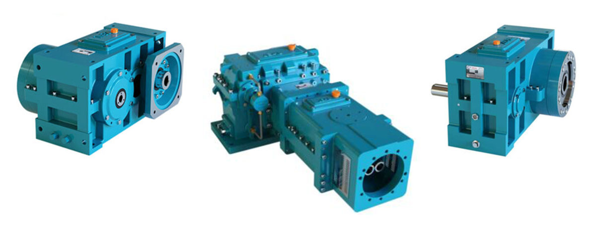
Every minute a rubber processing line stops unexpectedly, a plant loses output, misses shipment deadlines, and burns through maintenance budgets faster than planned. In a surprising number of these breakdowns, the root cause is not the mixer, the extruder, or the calender itself — it is the gearbox for rubber processing machines driving them. Gearboxes silently absorb enormous shock loads, fluctuating compound viscosity, and continuous duty cycles that few other mechanical components are ever asked to withstand. When a gearbox is undersized, poorly lubricated, or simply mismatched to the application, the results range from premature bearing failure to catastrophic gear-tooth breakage in the middle of a production run. Rubber processing — from mastication and mixing to extrusion, calendering, and molding — depends on precise, high-torque, low-speed power transmission. A gearbox for rubber processing machines is far more than a mechanical link between motor and machine; it is the single component that most often determines how consistently a plant can hit throughput targets, how long equipment lasts between overhauls, and how safely operators can run the line under peak load. This guide walks through why gearbox reliability matters so much in rubber processing, the types of gearboxes commonly used across mixers, extruders, calenders, and molding presses, the technical specifications that genuinely affect performance, the standards and materials that separate a durable unit from a short-lived one, and a practical framework for selecting, installing, and maintaining the right unit. Unplanned downtime tied to gear-drive failures remains one of the most common and most expensive problems reported across heavy-duty rubber and plastics processing plants, which makes gearbox knowledge one of the highest-leverage areas for any maintenance or engineering team to master. Whether you are specifying a gearbox for a brand-new production line, replacing a failed unit under time pressure, or simply trying to understand why your current equipment underperforms its rated life, the goal of this guide is the same: give you enough real engineering grounding to ask suppliers the right questions and make a decision you won’t regret two years into operation.
Quick Answer: A gearbox for rubber processing machines is a heavy-duty power transmission unit — typically helical, planetary, or worm-gear — that converts high motor speed into the high torque and low output speed needed to mix, extrude, calender, or mold rubber compounds reliably under continuous shock loading.
Why Gearbox Reliability Is a Make-or-Break Factor in Rubber Processing
The Unique Load Profile of Rubber Processing Equipment
Rubber processing machinery does not behave like a typical industrial conveyor or pump. A two-roll mill or internal mixer applies torque against a compound whose viscosity swings dramatically as it heats, softens, and cures during a single batch. An extruder screw fights back-pressure that spikes the moment a die partially blocks or a compound batch runs slightly stiffer than expected. A calender must hold torque steady across multiple rolls turning at precisely synchronized speeds while squeezing sheet stock to a tolerance of a fraction of a millimeter.
This means the gearbox for rubber processing machines is constantly asked to deliver high starting torque, absorb repeated shock loading, and run for extended periods at low output speeds — often the hardest combination of conditions a gear drive can face. Standard industrial gearboxes designed for steady, predictable loads (fans, conveyors, simple pumps) are rarely adequate here. Rubber machinery gearboxes need a higher service factor, more conservative bearing selection, and gear tooth geometry rated for shock rather than smooth, continuous torque.
The Real Cost of Gearbox Downtime
The financial impact of a failed gearbox rarely stops at the replacement part. A single gearbox failure on a mixing line can halt an entire batch, scrap partially processed compound, delay downstream extrusion or molding schedules, and trigger overtime labor to catch up on missed orders. Because most rubber processing gearboxes are custom-rated or long-lead-time items, an unplanned failure can mean days or weeks of waiting for a replacement, not hours.
Plants that treat gearbox selection and maintenance as an afterthought tend to experience the same failure patterns repeatedly: overheating from inadequate cooling, premature bearing wear from misalignment, and gear-tooth pitting from contaminated or degraded lubricant. Each of these is preventable with the right combination of gearbox design, correct sizing at the specification stage, and a disciplined maintenance schedule — the three themes this guide covers in detail.
There is also a safety dimension that is easy to underweight. A gearbox that is beginning to fail rarely gives a clean, instant warning; it tends to run louder, hotter, and rougher for days or weeks before an actual breakage, during which operators are working near a machine carrying degraded torque transmission and unpredictable behavior under load. Treating early warning signs — unusual noise, rising housing temperature, visible oil discoloration — as an immediate inspection trigger protects both equipment and personnel, not just production schedules.
Types of Gearboxes Used in Rubber Processing Machines
Rubber processing lines use several distinct gearbox architectures, and the right choice depends heavily on the specific machine — mixer, extruder, calender, or press — and the torque, speed, and space constraints involved.
Helical Gearboxes
Helical gearboxes are the most widely used type across rubber processing equipment because their angled gear teeth engage gradually rather than all at once, which spreads load across more tooth surface and reduces noise and vibration compared to straight-cut spur gears. This gradual engagement also helps absorb the shock loading typical of mixing and extrusion. Helical units are available in single-stage, double-stage, and triple-stage configurations, allowing engineers to hit a wide range of reduction ratios — often from roughly 5:1 up to 100:1 or more — while keeping the housing relatively compact. They are common on extruders, batch-off mills, and general-purpose drive applications where high efficiency (typically 96–98% per stage) and moderate footprint both matter.
Planetary Gearboxes
Planetary (epicyclic) gearboxes distribute torque across multiple gear sets arranged around a central sun gear, which lets them transmit very high torque in a compact housing. This makes them attractive for retrofits where space around an existing machine frame is limited, or for applications demanding extremely high torque density, such as heavy internal mixers and large batch presses. Planetary designs typically offer excellent torsional stiffness and lower backlash than comparable helical units, which benefits processes like calendering that depend on precise, synchronized roll speeds.
Worm Gearboxes
Worm gearboxes use a screw-like worm meshing with a toothed wheel to achieve very high single-stage reduction ratios, sometimes exceeding 60:1 or 100:1 in one compact stage. Their self-locking characteristic — the load side cannot easily back-drive the motor side — is useful on some auxiliary rubber-line equipment, such as slow-speed indexing tables or certain feed mechanisms. However, worm gearboxes are less efficient than helical or planetary designs (often 60–90% depending on ratio), generate more heat, and are generally reserved for lower-power, lower-duty-cycle applications rather than the main drive of a mixer or extruder.
Bevel-Helical and Right-Angle Gearboxes
Where a rubber processing machine’s layout requires the output shaft to run perpendicular to the motor — common on certain calender and roll-mill configurations — bevel-helical gearboxes combine a bevel gear stage for the directional change with helical stages for reduction and torque multiplication. These units let plant engineers fit a drive train into a constrained factory layout without sacrificing the load-handling advantages of helical gearing.
Cycloidal Gearboxes
Cycloidal gearboxes use an eccentric cam and roller-pin arrangement rather than conventional meshing teeth, which gives them exceptional shock-load tolerance and a very high torsional stiffness for their size. This makes them a strong option for applications with frequent start-stop cycling and sudden load spikes, such as indexing tables on molding lines or certain feed-roll drives where repeated impact loading would fatigue a conventional gear set faster. Cycloidal units tend to carry a higher unit cost than helical alternatives, so they are typically reserved for positions on the line where their shock-absorption advantage clearly outweighs the price premium.
Gear Motors vs. Standalone Gearboxes
Smaller rubber processing auxiliary equipment — batch conveyors, trimming stations, some feeding systems — often uses an integrated gear motor, where the motor and gearbox are supplied as a single compact unit. Larger primary drives on mixers, extruders, and mills almost always use a standalone gearbox coupled to a separate, often larger and more serviceable, electric motor. This separation matters for maintenance: a standalone gearbox can typically be serviced, realigned, or swapped without disturbing the motor or the rest of the drive train, and it also allows a plant to keep a single spare gearbox in stock that can be paired with more than one motor size if a process changes.
| Gearbox Type | Typical Efficiency | Best Suited For | Key Limitation |
| Helical | 96–98% per stage | Extruders, mills, general drives | Larger footprint at very high ratios |
| Planetary | 95–98% | High-torque, space-constrained retrofits | Higher unit cost |
| Worm | 60–90% | Slow-speed, low-duty auxiliary drives | Lower efficiency, more heat |
| Bevel-Helical | 94–97% | Right-angle layouts on mills/calenders | More complex housing/service |
Key Technical Specifications That Determine Gearbox Performance
Choosing between gearbox types is only half the job. The specification sheet is where most sizing mistakes actually happen, and it is worth understanding what each number really means for a rubber processing application.
Torque Rating and Service Factor
The output torque rating tells you how much twisting force the gearbox can deliver continuously, but the service factor is what protects the unit from the shock loads unique to rubber processing. A service factor of 1.5 means the gearbox is rated to handle 1.5 times its nominal load momentarily without damage — and for mixers and extruders processing compounds with unpredictable viscosity, a service factor at the higher end of the manufacturer’s range (often 1.4–2.0) is the safer choice, even though it usually means a physically larger and more expensive unit.
Reduction Ratio and Output Speed
Rubber processing equipment typically runs at low output speeds — a two-roll mill might turn at 10–30 RPM, while an internal mixer rotor might run even slower under load. Motors, by contrast, run efficiently at 1,000–1,500 RPM or higher. The reduction ratio bridges this gap, and getting it right is what allows the motor to operate near its efficient speed band while the process side gets the torque and speed it actually needs.
Thermal Rating and Cooling
Continuous operation at high torque generates heat inside the gearbox, primarily from gear meshing losses and bearing friction. The thermal rating specifies the maximum continuous power the gearbox can dissipate without exceeding a safe oil temperature, typically referenced against a defined ambient temperature (often 20°C or 25°C). Rubber processing gearboxes running near their thermal limit for long batch cycles frequently need auxiliary cooling — a finned housing, an oil cooler, or a forced-air fan — to avoid lubricant breakdown and accelerated bearing wear.
Bearing Selection and Radial/Axial Load Capacity
Bearings, not gear teeth, are the most common point of premature gearbox failure in rubber processing applications. Because mixer rotors and mill rolls impose significant radial and sometimes axial loads directly on the output shaft, bearing capacity — not just gear tooth strength — must be matched to the specific mounting arrangement and overhung load of the driven equipment.
Backlash and Torsional Rigidity
Backlash is the small amount of rotational play between meshing gear teeth, and while a few arc-minutes of backlash rarely matter on a simple mixer, it becomes critical on a calender, where two or more rolls must stay synchronized within a fraction of a millimeter across the full width of a rubber sheet. Excess backlash shows up as inconsistent sheet gauge, roll “hunting,” or vibration under load reversal. Planetary and precision helical gearboxes generally offer lower backlash and higher torsional rigidity than standard helical or worm units, which is why they are frequently specified on calender drives even at a higher unit cost.
Efficiency and Total Cost of Ownership
Efficiency differences between gearbox types look small on paper — a few percentage points between a helical and a worm unit — but compound significantly over years of continuous operation. A gearbox running at 85% efficiency instead of 97% on a large mixer drive can waste enough energy over its service life to cover a meaningful fraction of a higher-quality replacement unit’s purchase price, before even counting the reduced downtime and heat-related maintenance that typically come with the more efficient design. This is why total cost of ownership, not sticker price alone, should drive the final gearbox decision.
Housing Material and Sealing
Rubber processing plants are hot, often humid, and can involve fine particulate from compounding operations. Cast iron housings offer strong vibration damping for heavy shock-load applications, while some manufacturers offer aluminum housings for lighter-duty auxiliary drives where weight matters more than mass-driven vibration absorption. Shaft seals rated for the plant’s ambient conditions prevent both oil leakage out and contamination in — a detail that is easy to overlook on a spec sheet but drives a large share of long-term reliability.
| Parameter | Why It Matters for Rubber Processing |
| Output Torque (Nm) | Must cover peak, not just average, process load |
| Service Factor | Buffers against shock loading from compound viscosity swings |
| Reduction Ratio | Matches efficient motor speed to slow process-side speed |
| Thermal Rating (kW) | Prevents oil breakdown during long, continuous batch cycles |
| Radial/Axial Load Capacity | Protects bearings from mixer/mill overhung loads |
| Backlash | Affects synchronization accuracy on calenders |
| Housing Material | Balances vibration damping against weight and cost |
| IP Rating / Sealing | Protects against heat, humidity, and particulate ingress |
Industry Standards, Materials, and Lubrication Best Practices
Beyond gearbox type and headline specifications, three areas separate a gearbox that reaches its full design life from one that fails early: the engineering standards it was rated against, the materials used in its construction, and the lubricant strategy applied once it is in service.
Gear Rating Standards: AGMA and ISO 6336
Reputable gearbox manufacturers rate their gear sets against recognized engineering standards rather than relying on generic catalog numbers. AGMA (American Gear Manufacturers Association) standards and ISO 6336 both define how gear tooth strength, surface durability, and load capacity are calculated based on material, hardness, geometry, and operating conditions. When evaluating suppliers for a rubber processing gearbox, ask specifically whether the gear rating was calculated to AGMA or ISO 6336 methodology — a supplier that can produce this calculation on request is signaling a materially different level of engineering rigor than one that only points to a catalog torque figure.
Gear and Shaft Material Selection
Gear teeth on heavy-duty rubber processing gearboxes are typically manufactured from alloy steels such as 20CrMnTi or equivalent case-hardening grades, carburized and hardened to a surface hardness in the range of 58–62 HRC while retaining a tougher core to resist shock fracture. Output shafts see similarly high stress concentrations at keyways and bearing seats, so shaft material and heat treatment deserve the same scrutiny as the gears themselves — a shaft that is hard enough to resist wear but not tough enough to absorb shock loading is a common, avoidable failure point.
Lubricant Selection: Mineral, Synthetic, and Food-Grade Options
Mineral gear oils remain the most cost-effective choice for moderate-duty rubber processing applications with standard oil-change intervals. Synthetic gear oils cost more upfront but typically extend oil-change intervals two to four times longer, resist viscosity breakdown at higher sustained temperatures, and often pay for themselves through reduced maintenance labor on continuously running mixers and extruders. Food-grade (H1-rated) lubricants are required wherever incidental contact with rubber compounds destined for food-contact or pharmaceutical applications is a regulatory concern, and switching to food-grade oil after the fact often requires a full flush rather than a simple top-up, so it is worth specifying correctly from the start.
Housing Coatings and Corrosion Protection
Plants in humid coastal regions or those running washdown cycles between batches benefit from gearboxes with corrosion-resistant coatings on the housing and exposed fasteners, since surface corrosion around seal interfaces is a common precursor to the water ingress that ultimately damages bearings and lubricant quality.
How to Choose the Right Gearbox: A Step-by-Step Framework
Selecting a gearbox for rubber processing machines is a systematic exercise, not a catalog lookup. The following framework reflects how experienced mechanical engineers approach the decision.
Step 1: Define the Actual Load Profile, Not Just Nameplate Power
Start with real operating data rather than a motor’s nameplate rating alone. Log peak torque during compound loading, average torque through the batch cycle, and how frequently peak loads occur. If your plant has a variable-frequency drive on the motor, pull torque and current logs directly from the drive rather than estimating — most VFDs already record this data and it is far more reliable than a manual stopwatch-and-clamp-meter survey. A mixer that spikes to 150% of average torque every batch needs a very different service factor than one running a steady, predictable extrusion process, and no amount of careful ratio or bearing calculation later in the process can correct for starting with the wrong load number here.
Step 2: Calculate Required Reduction Ratio and Output Speed
Divide the motor’s rated speed by the process-required output speed to get the baseline reduction ratio, then check that ratio against the torque the gearbox must deliver at that reduced speed — torque and speed move inversely through a gear train, so a higher ratio increases available torque for a given motor power.
Step 3: Apply the Correct Service Factor for Shock Loading
Cross-reference the calculated load against the gearbox manufacturer’s service factor tables for “heavy shock load, uniform load 24-hour” duty — the classification most rubber mixing and extrusion applications fall under — rather than the lighter “uniform load, 8-hour” tables meant for conveyors and fans.
Step 4: Verify Thermal Capacity Against Duty Cycle
Confirm the gearbox’s continuous thermal rating covers your actual duty cycle, especially for batch mixers that may run near-continuously across multiple shifts. Manufacturers typically publish thermal ratings against a specific ambient temperature, so if your plant floor regularly runs hotter than that reference point — common in tropical climates or near curing ovens — derate the published figure accordingly rather than taking it at face value. If the calculated heat load exceeds the housing’s natural dissipation, specify an oil cooler or fan-cooling option up front rather than retrofitting it after overheating trips occur, since retrofitted cooling is almost always more expensive and less effective than a cooling package designed in from the start.
Step 5: Match Mounting, Shaft Configuration, and Space Constraints
Confirm foot-mounted, flange-mounted, or shaft-mounted configuration against the existing or planned machine frame, and check overhung load limits if the gearbox output shaft will carry a mill roll, mixer rotor, or extruder screw directly rather than through a flexible coupling.
Step 6: Confirm Lubrication Type and Maintenance Access
Decide between mineral, synthetic, or food-grade lubricant based on plant requirements and expected oil change intervals, and check that inspection ports, drain plugs, and breather locations are physically accessible once the gearbox is installed in its final position — a detail frequently missed during layout planning.
Step 7: Request Documentation and Compare Total Cost of Ownership
A slightly higher upfront price for a gearbox with a higher service factor, better sealing, and documented AGMA or ISO gear-rating compliance almost always costs less over five to ten years than repeated failures on an undersized unit. Ask suppliers for gear-rating calculations, bearing life (L10) estimates, and thermal capacity data rather than relying on catalog summaries alone.
Maintenance, Troubleshooting, and Real-World Failure Scenarios
Even a well-specified gearbox for rubber processing machines needs disciplined maintenance to reach its expected service life.
Routine Maintenance Practices
- Oil analysis on a fixed schedule — Sample gearbox oil every three to six months to catch water contamination, metal particles, or additive breakdown before they cause tooth or bearing damage.
- Vibration monitoring — Track baseline vibration signatures at commissioning, then monitor for drift that indicates developing bearing wear or misalignment.
- Thermal imaging during peak load — Scan housing temperatures during the heaviest batch cycles to catch developing hotspots before they become failures.
- Alignment checks after any coupling work — Re-verify shaft alignment any time a coupling, motor, or driven component is removed and reinstalled, since misalignment is one of the most common causes of premature bearing failure.
- Seal inspection at scheduled shutdowns — Replace shaft seals proactively rather than waiting for visible leakage, especially in humid or particulate-heavy plant environments.
Common Failure Patterns and Root Causes
Overheating and lubricant breakdown typically traces back to an undersized thermal rating for the actual duty cycle, a clogged or undersized cooling fan, or simply running the gearbox well past its recommended oil-change interval. Gear-tooth pitting and spalling usually results from insufficient service factor for shock loading, contaminated lubricant, or a reduction ratio that leaves the gearbox running near its torque limit continuously rather than only at peak. Premature bearing failure is most often caused by misalignment, excessive overhung load from a directly mounted mixer rotor or mill roll, or water ingress through a degraded shaft seal.
Spare Parts Strategy and Lead Time Planning
Because many rubber processing gearboxes are custom-rated or built to order, lead times for a full replacement unit can run from several weeks to a few months depending on size and manufacturer backlog. Plants running critical, hard-to-replace mixers or extruders reduce their downtime risk substantially by keeping a spare gearbox — or at minimum, high-wear spare parts such as bearings and seals — on site, and by establishing a relationship with a supplier or repair shop that can turn around a reconditioning job faster than a new-build lead time. Budgeting for this in advance is far cheaper than the production losses of an unplanned multi-week wait after a failure.
A Real-World Example
Consider a mid-sized rubber compounding plant that experienced repeated gearbox bearing failures on an internal mixer every eight to ten months, far short of the expected multi-year service life. Root-cause investigation found two compounding issues: the gearbox had been specified using average torque rather than peak batch-loading torque, leaving an inadequate service factor, and the shaft seal design was not rated for the plant’s high-humidity environment, allowing gradual water ingress into the lubricant. Re-specifying the replacement gearbox with a higher service factor rated for heavy shock loading, combined with an upgraded seal package, extended service life to beyond four years — illustrating how closely gearbox selection and maintenance are linked to real operating conditions rather than catalog defaults.
Gearbox Solutions Built for Rubber Processing Equipment
If your plant is dealing with recurring gearbox failures, unplanned downtime, or a retrofit that needs more torque density in a tighter footprint, the fastest path forward is working with a supplier that actually engineers to your load profile rather than selling from a generic catalog page. The right partner reviews your peak and average torque data, applies the correct service factor for shock loading, and confirms thermal and bearing capacity against your real duty cycle before a gearbox is ever built.
Look for a few concrete signals of that kind of partner: gear-rating calculations and bearing L10 life estimates provided as standard documentation, in-house engineering support for OEM-compatible and drop-in replacement units, and manufacturing quality control that includes dimensional, hardness, and load testing before dispatch — not just a certificate on paper. It also helps to work with a supplier who can support both new-build specification and reverse-engineered replacements from an existing machine’s drawing or sample, since many rubber processing lines run older frames where the original gearbox model is no longer in production.
Plants that have standardized on properly engineered, correctly sized gearboxes consistently report fewer unplanned stoppages and longer intervals between overhauls compared to relying on undersized, off-the-shelf units. If you’re evaluating a new gearbox for a mixer, extruder, calender, or press, our engineering team can review your torque and duty-cycle data and recommend a correctly rated unit — including OEM-compatible replacements for existing machine frames — so you get a gearbox sized for how your line actually runs, not just what a catalog page assumes it runs like.
Frequently Asked Questions
Q1. What is the best type of gearbox for a rubber mixing mill?
For most rubber mixing mills, a helical or planetary gearbox is the best fit because both handle the heavy shock loading and continuous high-torque demand of mixing far better than a worm gearbox. Helical units are the more common, cost-effective choice, while planetary designs are preferred when space around the mixer frame is limited but very high torque density is still required.
Q2. How long should a rubber processing machine gearbox last?
A correctly specified and maintained gearbox for rubber processing machines should typically run five to ten years, or considerably longer with rigorous oil analysis and alignment practices. Gearboxes that fail within one to two years almost always point to undersizing, an inadequate service factor, or a maintenance gap rather than normal wear.
Q3. What service factor should I use for a rubber extruder gearbox?
Rubber extruders generally fall under “heavy shock load” duty classifications, so a service factor between 1.4 and 2.0 is common, depending on the specific compound viscosity range and how frequently die pressure spikes occur. Always check the actual peak torque data against the manufacturer’s rating tables rather than assuming a default value.
Q4. Can I retrofit a planetary gearbox onto an existing mixer frame?
Yes, planetary gearboxes are frequently used specifically for retrofits because their compact, high-torque-density design often fits into the same footprint as an older, larger helical or worm unit. Confirm output shaft dimensions, mounting bolt pattern, and overhung load rating against your existing rotor before finalizing the retrofit.
Q5. Why does my gearbox keep overheating during long production runs?
Overheating during extended runs usually means the gearbox’s thermal rating is too close to, or below, the actual continuous heat generated by your duty cycle, often made worse by a clogged cooling fan, low oil level, or degraded lubricant well past its change interval. Checking thermal capacity against real multi-shift duty cycles at the specification stage prevents most of these cases.
Q6. Is a worm gearbox ever suitable for rubber processing equipment?
Worm gearboxes are generally reserved for lower-power, slower-duty auxiliary equipment on a rubber processing line, such as indexing tables or light feed mechanisms, rather than the main drive of a mixer or extruder, because their lower efficiency and higher heat generation make them a poor fit for continuous heavy-load duty.
Q7. What is the biggest mistake plants make when selecting a rubber machinery gearbox?
The most common and costly mistake is sizing the gearbox to average operating torque instead of peak shock-load torque, which leaves an inadequate service factor and leads to premature bearing or gear-tooth failure well before the unit’s expected service life.
Q8. Should I switch to synthetic gear oil for my rubber processing gearbox?
Synthetic gear oil is generally worth the higher upfront cost for continuously running mixers and extruders because it resists viscosity breakdown at sustained high temperatures and typically extends oil-change intervals two to four times longer than mineral oil, which often offsets its price premium through reduced maintenance labor and downtime alone.
Q9. Can an existing gearbox be repaired instead of replaced?
In many cases, yes — gear sets, bearings, and seals can often be reconditioned or replaced within the original housing if the housing itself and the gear teeth are not structurally damaged, which is typically far more cost-effective than a full replacement, provided a qualified shop inspects the unit first.
Conclusion
Gearboxes for rubber processing machines carry far more responsibility than their compact housings suggest. They absorb the shock loading of mixing, hold the precise torque and speed a calender needs to run rolls in sync, and determine — more than almost any other single component — how much unplanned downtime a plant experiences over the life of its equipment. Getting the selection right starts with real load data rather than nameplate assumptions, applying an honest service factor for heavy shock duty, and verifying thermal and bearing capacity against the actual duty cycle rather than a generic catalog rating.
Across helical, planetary, worm, cycloidal, and bevel-helical designs, the right choice always comes back to matching the gearbox’s engineering to the specific torque, speed, space, and environmental demands of your mixer, extruder, calender, or press. Combined with a disciplined maintenance routine — oil analysis, vibration monitoring, alignment checks, and proactive seal replacement — a correctly specified gearbox can comfortably outlast a poorly matched one by several years, saving far more in avoided downtime than it ever cost upfront.
None of this requires guesswork. Real load data, an honest service factor, and documentation you can actually verify — gear-rating calculations, bearing life estimates, thermal capacity figures — turn gearbox selection from a catalog gamble into a straightforward engineering decision, and that shift alone is often the difference between a gearbox that quietly runs for a decade and one that becomes a recurring line item in next year’s maintenance budget.
If your plant is experiencing recurring gearbox issues or planning a new line, get in touch with our engineering team for a free load-profile review and gearbox recommendation tailored to your equipment.
