
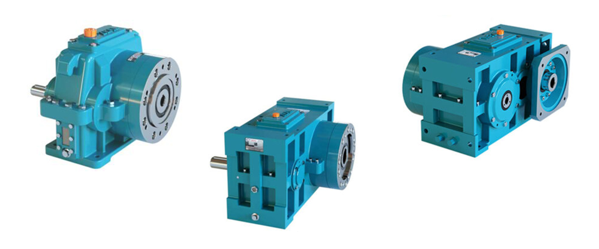
Torque is the single most important mechanical parameter in a plastic extruder gearbox — more important than gear ratio, more important than input speed, and more important than physical size. It is the output torque of the gearbox that actually pushes the plastic melt through the barrel and die. Get the torque sizing right and the machine runs reliably, efficiently, and productively for years. Get it wrong — in either direction — and the consequences range from premature gearbox failure to permanently underperforming production. Yet torque remains one of the least understood parameters among the engineers, production managers, and procurement professionals who specify and operate extrusion equipment. Many machines are commissioned with gearboxes selected on price, or on the basis of a rough size match to a previous machine, without ever calculating whether the output torque is actually sufficient for the material being processed at the required production rate. Others are over-specified to the point where the gearbox operates at a tiny fraction of its rated capacity — wasting capital expenditure and skewing maintenance planning. This comprehensive guide changes that. It explains exactly what torque is in the context of plastic extrusion, how torque requirements arise from the physics of the extrusion process, how to calculate the torque demand for any material and screw combination, how to correctly apply service factors, how torque requirements vary across different plastic materials and applications, and how to diagnose and solve torque-related problems on existing extrusion lines. Every formula is explained with worked examples, and every table is filled with the specific values that practising engineers need.
What is Torque? — The Engineering Definition for Extrusion
Torque is the rotational equivalent of force. While linear force pushes or pulls an object in a straight line, torque rotates an object around an axis. In the context of a plastic extruder gearbox, torque is the rotational force that the gearbox output shaft applies to the extruder screw — the turning effort that causes the screw to rotate within the barrel.
Torque is measured in Newton-metres (Nm). One Newton-metre of torque is the rotational force produced by a force of one Newton applied at a perpendicular distance of one metre from the axis of rotation. In practical terms, a gearbox with an output torque of 5,000 Nm is applying a rotational force equivalent to a 500 kg weight acting at a lever arm of one metre from the screw centreline — a substantial mechanical force that is typical for medium-sized extrusion applications.
Torque — The Fundamental Definition
Torque (Nm) = Force (N) x Radius (m)
In a gearbox context:
Torque (Nm) = the rotational effort applied to the output shaft
Higher torque = more turning force available to drive the extruder screw
Lower torque = less turning force — insufficient to push viscous melt through the barrel
Understanding torque is essential because the plastic extrusion process is fundamentally a torque-driven process. The energy required to plasticise solid plastic granules, push the resulting melt along the barrel under high pressure, and force it through the die geometry is delivered entirely as torque through the extruder screw. The gearbox is the device that converts the motor’s high-speed, low-torque rotation into the low-speed, high-torque output that the screw requires.
Torque vs Force vs Power — Understanding the Relationships
Three mechanical quantities are interrelated in every extruder drive system: torque, force, and power. Confusion between these terms is one of the most common sources of error in gearbox specification. Understanding the precise relationship between them is fundamental to correct torque calculation.
- Torque (Nm): The rotational force the gearbox delivers to the screw. This is what drives the extrusion process. It is what must be matched to the process requirement.
- Power (kW): The rate at which energy is delivered. Power is the product of torque and rotational speed. Two gearboxes can deliver the same power at very different combinations of torque and speed.
- Force (kN): The linear force the screw applies to the plastic melt. In the axial direction, this becomes the thrust force on the gearbox thrust bearing. In the tangential direction, it relates to the torque through the screw radius.
A critically important point: two gearboxes driven by the same motor can have very different output torque ratings, depending on their gear ratios. A higher gear ratio multiplies torque (at the cost of speed). A lower gear ratio gives more speed but less torque. This is why specifying a gearbox on motor power alone — without calculating the required output torque — is always an incomplete and potentially dangerous approach.
Where Does Torque Demand Come From in an Extruder?
To correctly size the torque requirement of an extruder gearbox, it is necessary to understand exactly where the torque demand originates — what physical processes in the extruder consume torque and how large each contribution is.
Source 1 — Solid Conveying and Compression Zone Resistance
In the feed zone and early compression zone of the extruder barrel, the screw must mechanically convey solid plastic granules forward and compress them. The solid plastic must be pushed against the barrel wall by the screw flights, generating friction that propels the material forward. This solid conveying and compression resistance is the torque contribution from the unmelted material zone, and it is most significant during cold startup, when the material is solid and the barrel is not yet at operating temperature.
Source 2 — Plasticisation and Melting Energy
As the plastic material moves through the transition zone of the barrel, it undergoes melting driven by a combination of conductive heat from the barrel heaters and shear heat generated by the mechanical working of the screw. The energy required for this phase change from solid to melt is delivered primarily as mechanical torque through the screw — the viscous melt must be continuously sheared and worked to achieve full plasticisation. For high-molecular-weight materials and for materials with high melting enthalpies, this plasticisation torque contribution is substantial.
Source 3 — Melt Pumping and Die Pressure
In the metering zone of the barrel, the fully plasticised melt must be pressurised to overcome the resistance of the die geometry and pushed through the die at the required volumetric flow rate. This is the melt pumping contribution to torque demand, and it is determined by the melt viscosity of the material, the die geometry, the melt temperature, and the required output rate. For applications with highly restrictive die geometries — such as complex PVC profiles, thin-wall pipe, or fine medical tubing — the die pressure can be very high (300 to 700 bar), making the melt pumping torque contribution the dominant component of total screw torque demand.
Source 4 — Viscous Dissipation and Shear Resistance
As the screw flights move through the viscous melt in the metering zone, they must continuously shear the melt film between the screw root and the barrel wall. This viscous shearing requires torque in proportion to the melt viscosity, the screw speed, and the screw channel geometry. For high-viscosity materials such as rigid PVC, HDPE with high molecular weight, and filled compounds, this viscous dissipation term is significant and cannot be neglected in the torque calculation.
Core Torque–Power–Speed Formulas
FORMULA 1 — Power from Torque and Speed:
Power (kW) = Torque (Nm) x Speed (RPM) / 9,550
FORMULA 2 — Torque from Power and Speed:
Torque (Nm) = Power (kW) x 9,550 / Speed (RPM)
FORMULA 3 — Output Torque from Motor Power (with gearbox efficiency):
Output Torque (Nm) = Motor Power (kW) x 9,550 / Output Speed (RPM) x Efficiency
FORMULA 4 — Output Speed from Gear Ratio:
Output Speed (RPM) = Motor Speed (RPM) / Gear Ratio
The constant 9,550 converts between kW, Nm, and RPM (derived from 2π/60 x 1000).
Worked Example 1 — Calculating Available Output Torque
A 75 kW, 4-pole motor (1,450 RPM rated speed) drives an extruder through a helical gearbox with a gear ratio of 25:1 and a mechanical efficiency of 97%. What is the available output torque at the extruder screw?
Worked Example 1 — Output Torque Calculation
Step 1 — Calculate output speed:
Output speed = 1,450 / 25 = 58 RPM
Step 2 — Calculate available output torque:
Output torque = 75 x 9,550 / 58 x 0.97
Output torque = 716,250 / 58 x 0.97
Output torque = 12,349.1 x 0.97
Output torque = 11,979 Nm ≈ 11,980 Nm
Result: The gearbox can deliver approximately 11,980 Nm to the extruder screw at rated motor power.
Worked Example 2 — Calculating Required Motor Power from Torque Demand
An extruder processing HDPE requires 9,500 Nm at the screw at an operating speed of 65 RPM. What minimum motor power is needed, assuming a gearbox efficiency of 97%?
Worked Example 2 — Required Motor Power Calculation
Step 1 — Calculate power required at gearbox output:
Output power required = 9,500 x 65 / 9,550 = 64.7 kW
Step 2 — Account for gearbox efficiency to find motor input power:
Motor power required = Output power / Efficiency = 64.7 / 0.97 = 66.7 kW
Step 3 — Select next standard motor size above calculated requirement:
Select 75 kW motor (next standard size above 66.7 kW)
Result: A 75 kW motor with this gearbox gives a 12% torque reserve above the process demand.
Worked Example 3 — Checking Whether an Existing Gearbox Has Sufficient Torque
An existing 55 kW motor drives an extruder through a gearbox with gear ratio 20:1, efficiency 97%, and a rated output torque of 10,500 Nm. The process requires 9,800 Nm at 72 RPM. Is the gearbox adequate?
Worked Example 3 — Torque Adequacy Check
Step 1 — Calculate available output torque:
Output speed = 1,450 / 20 = 72.5 RPM
Output torque = 55 x 9,550 / 72.5 x 0.97 = 7,037 Nm
Step 2 — Compare available torque to process requirement:
Available: 7,037 Nm vs Required: 9,800 Nm
Deficit: 2,763 Nm (gearbox UNDER-SIZED for the process)
Step 3 — Check rated torque vs available torque:
Rated output torque = 10,500 Nm (gearbox rating itself is adequate)
But motor power only delivers 7,037 Nm — motor is the limiting factor
Result: The gearbox rating is adequate but the motor is undersized.
Solution: Upgrade motor to 75 kW to deliver the required 9,800 Nm.
Worked Example 3 illustrates an important point that is frequently overlooked: the gearbox torque rating and the motor-limited torque are two different values. The gearbox has a mechanical torque rating — the maximum torque its gears and bearings can sustain. But the actual torque available to the process is limited by whichever is lower: the gearbox mechanical rating or the torque the motor can deliver. Both must be checked independently.
Step-by-Step: How to Calculate Your Extruder Torque Requirement
The following step-by-step procedure provides a systematic method for calculating the torque requirement of any plastic extruder gearbox. Following this process for every new machine specification or gearbox replacement will ensure that the selected unit is correctly sized for the application.
- Step 1 — Define the Process Requirements: Establish the plastic material to be processed (including its melt viscosity class), the extruder screw diameter (mm), the screw L/D ratio, the required maximum throughput rate (kg/h), and the required screw speed range (RPM minimum to RPM maximum).
- Step 2 — Determine the Specific Torque Demand: Use the material-specific torque data from Section 6 of this guide, or from the extruder manufacturer’s process data, to establish the specific torque demand for your material. Specific torque demand is typically expressed in Nm per cm³ of screw channel volume, or can be derived from the motor power data of existing similar machines.
- Step 3 — Calculate Screw Torque from Motor Power Data: If motor power data from an existing similar machine is available, use Formula 2 (Torque = Power x 9,550 / Speed x Efficiency) to back-calculate the process torque at typical operating conditions. This empirical approach is often more reliable than theoretical calculations for complex materials.
- Step 4 — Calculate Torque from Die Pressure (if die data is available): For applications where the die pressure at maximum output is known or can be estimated from die simulation, the screw discharge torque component can be estimated from the relationship between melt pressure, screw diameter, and screw channel geometry.
- Step 5 — Identify the Maximum Torque Condition: The maximum torque demand does not necessarily occur at the maximum screw speed. For many materials, torque demand peaks at lower screw speeds when the material is cold or when a high back-pressure die is used. Identify the worst-case combination of screw speed, material temperature, and die restriction.
- Step 6 — Apply the Service Factor: Multiply the calculated maximum torque demand by the appropriate service factor (see Section 5 for service factor selection guidance). The result is the required gearbox rated output torque.
- Step 7 — Select a Gearbox with a Rated Torque Equal to or Greater Than the Required Value: The gearbox rated output torque must meet or exceed the service-factored torque calculated in Step 6. Verify also that the gear ratio gives the correct output speed at the motor’s rated speed, and that the thrust bearing capacity is adequate for the screw axial load.
- Step 8 — Verify the Motor Power: Confirm that the motor, operating at rated power at the gearbox input, can deliver the required output torque at the required output speed. Use Formula 3 to calculate the motor-limited output torque and compare it to the process requirement.
- Step 9 — Document the Calculation: Record the complete calculation, including all input parameters and assumptions, so that it can be reviewed, checked, and referenced when the gearbox is eventually maintained or replaced.
Understanding the Service Factor — Why It Is Not Optional
The service factor is a multiplier applied to the calculated process torque demand before specifying the gearbox rated output torque. It provides a margin between the design point torque and the gearbox’s physical capability — a buffer that absorbs the unpredictable torque peaks, process variations, and degradation effects that inevitably occur in real production environments.
Selecting a gearbox rated exactly at the calculated process torque — without any service factor margin — means the gearbox is operating at 100% of its rated capacity under normal conditions. Any torque peak above the calculated value will exceed the gearbox rating, potentially causing tooth fatigue damage that accumulates with each overload event until premature failure occurs. The service factor is not an optional safety luxury — it is a fundamental engineering requirement for any gearbox intended to provide a long service life.
Service Factor Selection Guide
| Operating Condition / Application Type | Recommended Service Factor | Rationale |
| Steady load, single material, no frequent starts | 1.25 | Minimum acceptable margin for continuous extrusion duty |
| Standard extrusion — occasional material changes | 1.4 – 1.5 | Accounts for viscosity variation between material batches |
| Frequent start-stop cycles or frequent material changes | 1.5 – 1.75 | Startup torque peaks and variable load profiles |
| Processing of high-viscosity or filled materials | 1.5 – 2.0 | Unpredictable viscosity spikes and cold-start torque peaks |
| Cold-start on rigid PVC or engineering polymers | 2.0 – 2.5 | Very high startup torque before material reaches melt temperature |
| Twin screw compounding with high filler loading | 1.75 – 2.25 | Severe and unpredictable load variations during compounding |
| Emergency overload protection required | 2.5+ | Critical machines where breakdown would cause major production loss |
The Service Factor Misconception
A common mistake is to believe that a higher service factor simply means a more expensive gearbox with wasted capacity.
In reality, service factor represents the ratio between the gearbox’s capability and the worst-case process demand.
A gearbox running at SF 1.5 is operating at 67% of its rated capacity under normal conditions — with a 50% reserve for peaks.
This reserve is what separates a gearbox that lasts 15 years from one that fails in 3 years.
Never select a service factor below 1.25 for any continuous extrusion application.
How Service Factor Affects Gearbox Selection in Practice
To illustrate the practical impact of service factor selection, consider an extrusion process with a calculated maximum torque demand of 8,000 Nm:
| Service Factor | Required Gearbox Rating | Operating Load Level | Expected Service Life |
| 1.0 (no margin) | 8,000 Nm | 100% of rating | Poor — overload damage accumulates rapidly |
| 1.25 | 10,000 Nm | 80% of rating | Acceptable — minimum for steady load |
| 1.5 | 12,000 Nm | 67% of rating | Good — adequate margin for normal extrusion |
| 2.0 | 16,000 Nm | 50% of rating | Excellent — handles peaks and hard starts |
Torque Requirements by Plastic Material Type
The torque demand of a plastic extrusion process is strongly influenced by the melt viscosity of the material being processed. Melt viscosity — the resistance of the plasticised material to flow — varies enormously between different plastic types, and also varies significantly within the same material type depending on molecular weight, additive content, melt temperature, and shear rate.
The following table provides specific torque demand guidance for the most common plastic materials processed in industrial extrusion, expressed as a relative torque index (where LDPE at standard conditions = 1.0) and as indicative specific torque values for a reference 60 mm diameter screw:
| Plastic Material | Relative Torque Index | Melt Viscosity Class | Typical Screw Speed (RPM) | Specific Torque Demand* | Service Factor Guidance |
| LDPE | 1.0 (baseline) | Low | 80–150 | Low | 1.25–1.4 |
| LLDPE | 1.1–1.3 | Low-Medium | 80–140 | Low | 1.25–1.4 |
| HDPE (std MW) | 1.5–2.0 | Medium | 50–100 | Medium | 1.4–1.6 |
| HDPE (high MW) | 2.2–3.0 | Medium-High | 30–70 | High | 1.5–1.75 |
| PP Homopolymer | 1.6–2.2 | Medium | 50–100 | Medium | 1.4–1.6 |
| PP Copolymer | 1.8–2.4 | Medium | 50–90 | Medium | 1.5–1.65 |
| Soft PVC | 2.0–2.8 | Medium-High | 30–60 | Medium-High | 1.5–1.75 |
| Rigid PVC (uPVC) | 3.5–5.0 | Very High | 15–35 | Very High | 1.75–2.5 |
| PET | 1.2–1.6 | Low-Medium | 60–100 | Low-Medium | 1.4–1.5 |
| ABS | 2.0–2.8 | Medium-High | 40–80 | Medium-High | 1.5–1.75 |
| Polycarbonate (PC) | 2.5–3.5 | High | 30–60 | High | 1.6–2.0 |
| PMMA (Acrylic) | 2.2–3.0 | High | 30–60 | High | 1.6–2.0 |
| Nylon PA6 | 1.3–1.8 | Low-Medium | 50–80 | Low-Medium | 1.4–1.6 |
| Nylon PA66 | 1.4–2.0 | Medium | 40–80 | Medium | 1.5–1.65 |
| TPU | 1.8–2.5 | Medium | 40–70 | Medium | 1.5–1.75 |
| WPC (30% wood) | 3.0–4.5 | High | 20–50 | Very High | 1.75–2.25 |
| WPC (50%+ wood) | 4.5–6.5 | Very High | 15–35 | Extreme | 2.0–2.5 |
| CaCO3 filled (40%+) | 3.0–5.0 | High | 20–50 | Very High | 1.75–2.5 |
| Fibre-glass filled | 3.5–5.5 | Very High | 15–40 | Very High | 2.0–2.5 |
*Specific torque demand values are relative indicators for comparative purposes. Exact torque values depend on screw diameter, L/D ratio, melt temperature, screw design, and die pressure. Always calculate torque from actual process data for critical applications.
The table makes clear that the torque requirement for rigid PVC and highly filled compounds is dramatically higher than for standard polyolefins. A gearbox correctly sized for LDPE film extrusion may be severely undersized if the same machine is later used to process rigid PVC or high-filler compounds — a material change that requires a full torque recalculation before proceeding.
How Screw Diameter and L/D Ratio Affect Torque Demand
Two screw geometry parameters have a direct and significant effect on the torque demand of the extrusion process: the screw diameter and the length-to-diameter ratio (L/D ratio). Understanding these relationships is essential for correct torque specification across different machine sizes.
Effect of Screw Diameter on Torque
Torque demand scales strongly with screw diameter. A larger diameter screw has greater channel volume (more material being processed per revolution), greater surface area in contact with the melt (more viscous shear resistance), and a larger pitch circle at which the drag forces act. As a general rule, torque demand scales approximately with the cube of the screw diameter ratio:
Torque Scaling with Screw Diameter
Torque ratio ≈ (D2 / D1)³
Example: Scaling from a 60mm screw to a 90mm screw:
Torque ratio = (90 / 60)³ = 1.5³ = 3.375
Result: A 90mm screw requires approximately 3.4x more torque than a 60mm screw
at the same screw speed and material conditions.
This is why large-diameter extruders have dramatically higher gearbox torque ratings
than smaller machines even when processing the same material.
| Screw Diameter (mm) | Relative Torque Factor | Typical Torque Range (Nm) — HDPE | Typical Torque Range (Nm) — PVC | Typical Motor Power |
| 25 mm | 0.07 | 200 – 600 Nm | 400 – 1,200 Nm | 2.2 – 7.5 kW |
| 35 mm | 0.20 | 600 – 1,500 Nm | 1,200 – 3,000 Nm | 5.5 – 18.5 kW |
| 45 mm | 0.42 | 1,200 – 3,000 Nm | 2,500 – 6,000 Nm | 11 – 37 kW |
| 60 mm | 1.00 | 3,000 – 7,000 Nm | 6,000 – 15,000 Nm | 22 – 75 kW |
| 75 mm | 1.95 | 5,500 – 13,000 Nm | 11,000 – 28,000 Nm | 45 – 132 kW |
| 90 mm | 3.38 | 9,000 – 22,000 Nm | 18,000 – 50,000 Nm | 75 – 220 kW |
| 110 mm | 6.10 | 16,000 – 40,000 Nm | 32,000 – 90,000 Nm | 132 – 400 kW |
| 130 mm | 10.1 | 26,000 – 65,000 Nm | 52,000 – 150,000 Nm | 220 – 630 kW |
| 150 mm | 15.6 | 40,000 – 100,000 Nm | 80,000 – 230,000 Nm | 315 – 900 kW |
Effect of L/D Ratio on Torque
The L/D ratio — the ratio of the active screw length to the screw diameter — determines how much barrel length is available for melting, mixing, and pressurising the material. A higher L/D ratio provides more barrel length for thermal and mechanical processing, which generally results in better melt quality and more consistent output. However, a longer screw also has greater surface contact area with the melt, which increases the viscous drag torque component.
As a practical guideline, increasing the L/D ratio from 24 to 30 (a 25% increase in screw length) typically increases the torque demand by approximately 10% to 20%, depending on the material and process conditions. When specifying a gearbox for a new extrusion line with a long-barrel screw (L/D 30 or above), this additional torque contribution should be explicitly included in the calculation.
Startup Torque vs Running Torque — The Critical Difference
One of the most common and costly errors in extruder gearbox sizing is selecting the gearbox based solely on the steady-state running torque — the torque required to drive the extruder at its normal operating speed and temperature — without accounting for the much higher startup torque that occurs every time the machine is started from cold or restarted after a material purge.
Why Startup Torque is Much Higher Than Running Torque
When an extruder is started from cold, the plastic material in the barrel is either solid (if the machine has been idle with material in the barrel) or highly viscous cold melt. The barrel heaters require time to bring the material to processing temperature — during which the screw must rotate through material that is far more viscous and resistant than at normal operating temperature. The torque required to rotate the screw through cold, high-viscosity material can be two to five times the steady-state running torque.
For rigid PVC, engineering polymers, and highly filled compounds, the cold-start torque can be extreme. Rigid PVC that has not fully reached its processing window has viscosity many times higher than at normal melt temperature, and attempting to run the screw at full speed before the material has melted can generate torque peaks that far exceed the running torque specification.
| Material | Typical Running Torque | Typical Cold-Start Torque | Startup Factor |
| LDPE / LLDPE | Baseline | 1.3 – 1.6x running | 1.3 – 1.6x |
| HDPE (std MW) | 1.5 – 2.0x | 2.0 – 3.0x running | 1.3 – 1.8x |
| HDPE (high MW) | 2.2 – 3.0x | 3.5 – 5.0x running | 1.5 – 2.0x |
| PP | 1.6 – 2.2x | 2.5 – 3.5x running | 1.4 – 1.8x |
| Soft PVC | 2.0 – 2.8x | 3.0 – 4.5x running | 1.5 – 2.0x |
| Rigid PVC (uPVC) | 3.5 – 5.0x | 6.0 – 12.0x running | 1.7 – 3.0x |
| PC / PMMA | 2.5 – 3.5x | 4.0 – 7.0x running | 1.6 – 2.5x |
| WPC / Filled | 4.0 – 6.5x | 7.0 – 15.0x running | 1.75 – 3.0x |
Critical Startup Torque Warning
For rigid PVC, the cold-start torque can reach 6 to 12 times the normal running torque.
If the gearbox is sized only for running torque with a 1.5 SF, it will be overloaded every time the machine starts from cold.
This repeated cold-start overloading causes cumulative gear tooth fatigue that leads to premature failure.
For PVC, engineering polymers, and highly filled compounds:
— Always use the cold-start torque (not running torque) as the basis for gearbox sizing
— Or implement a controlled warm-up procedure that prevents full-speed screw rotation until melt temperature is reached
— Or install an overload protection device (torque limiting coupling) to protect the gearbox during cold starts
Best Practice: Warm-Up Procedure to Protect the Gearbox
The most effective and low-cost protection against cold-start torque damage is a controlled warm-up procedure. Before bringing the extruder screw to operating speed, the barrel heaters should be given sufficient time to bring the material temperature close to the processing window. For rigid PVC, a minimum warm-up time of 20 to 30 minutes from cold is typical before the screw should be started, and even then at low speed initially (10 to 20% of normal operating speed) until the melt is fully established.
How to Read and Verify a Gearbox Torque Rating
Every extruder gearbox supplied by a reputable manufacturer is provided with a technical data sheet that includes the gearbox torque rating. However, the torque rating on a gearbox datasheet can be expressed in several different ways — and misunderstanding which rating applies to which condition can result in a gearbox being used beyond its capability.
| Torque Rating Term | Definition | How to Use It in Selection |
| Rated / Nominal Output Torque | The continuous torque the gearbox can deliver indefinitely under normal operating conditions at rated input speed and temperature. | This is the primary selection parameter. Must exceed the service-factored process torque demand. |
| Peak / Overload Torque | The maximum torque the gearbox can sustain for short periods (typically defined as 1 to 10 seconds). Usually 150% to 250% of rated torque. | Used to check that cold-start or process peak torques do not cause immediate failure. Must not be sustained continuously. |
| Thermal Rating | The maximum continuous torque limited by heat generation and gearbox thermal capacity. May be lower than the mechanical rating at high ambient temperatures. | Must be checked for high-ambient or tropical environments. If thermal rating is lower than mechanical rating, use the thermal rating for selection. |
| Dynamic Rating | The torque capacity under dynamic (cyclically varying) load conditions, accounting for fatigue life. Often expressed as a life-based rating (e.g. at 20,000 hours L10h). | Relevant for applications with significant load variation. For steady-state extrusion, the rated torque is the primary parameter. |
| Emergency Stop Torque | The maximum torque that can be applied without immediate catastrophic failure — typically the yield or fracture limit of the gear teeth. Much higher than rated torque. | For reference only — operation at this level will cause damage. Never use for selection. |
When comparing gearbox datasheets from different manufacturers, always verify that the torque ratings quoted are on the same basis — rated continuous torque, not peak torque. Some manufacturers quote peak or overload torque prominently because it is a larger and more impressive number, while the continuous rated torque (the relevant value for extrusion) is lower. Always ask specifically for the rated continuous output torque at the operating input speed.
Torque Overload — Causes, Symptoms, and Prevention
Torque overload — operating the extruder gearbox above its rated output torque — is the single most common cause of premature gearbox failure in plastic extrusion applications. It causes damage that is often invisible initially but accumulates progressively until sudden, catastrophic failure.
Primary Causes of Torque Overload
- Cold Starting with Insufficient Warm-Up: As described in Section 8, starting the screw at full speed before the material has reached processing temperature generates torque peaks many times the running torque.
- Processing a More Viscous Material Than the Gearbox Was Rated For: Changing to a higher-molecular-weight grade, a more filled compound, or a fundamentally different (higher-viscosity) material type without recalculating the torque requirement.
- Running at Excessive Back Pressure: Using a very restrictive die, a partially blocked screen pack, or running at higher melt pressure than the original design basis, all increase the melt pumping torque component above the original specification.
- Increasing Screw Speed Beyond the Original Design Basis: Running the motor above its rated speed (via VSD over-frequency) to increase throughput increases both the shear torque component and the die pumping torque.
- Gearbox Undersized at Original Specification: A fundamental design error where the torque requirement was never correctly calculated and the gearbox was selected based on price, physical size, or rough comparison rather than systematic torque analysis.
Symptoms of Torque Overload
- Motor Overcurrent Trips: The VSD or motor protection relay trips on overcurrent — indicating that the motor is being asked to deliver more torque than it can sustain at the operating speed.
- Increased Gearbox Noise: A change in the character of gearbox noise — typically an increase in tone or the appearance of new irregular sounds — can indicate gear tooth stress or early fatigue damage.
- Elevated Gearbox Temperature: Sustained torque overload increases the gear mesh stress and friction, generating additional heat that raises the gearbox operating temperature above its normal level.
- Oil Discolouration and Metallic Particles: Accelerated gear tooth wear from chronic overloading produces fine metallic particles that discolour the oil and collect on the drain plug magnet.
- Progressive Loss of Screw Speed: As gear tooth damage progresses, the gearbox may develop play in the gear mesh (increased backlash) that causes the screw speed to become irregular or to drop below the set point.
Prevention Strategies
- Correct Initial Sizing with Adequate Service Factor: The fundamental prevention — size the gearbox correctly from the start, with a service factor appropriate for the most demanding material and condition.
- Implement and Enforce the Warm-Up Procedure: Particularly for PVC and engineering polymers, a documented and enforced warm-up protocol prevents the most common cause of cold-start overloading.
- Install a Torque-Limiting Coupling: A torque-limiting (overload protection) coupling between the motor and gearbox input shaft disengages automatically when the torque exceeds a set threshold, protecting the gearbox from occasional unexpected overloads.
- Monitor Motor Current: Motor current is directly proportional to motor torque. Installing a current monitoring display in the operator panel allows operators to observe the gearbox loading in real time and respond to sustained high-current conditions before damage occurs.
- Recalculate Torque Before Any Material Change: Any change to the material specification that could significantly increase melt viscosity should trigger a torque recalculation before the new material is run.
Torque Under-Loading — Causes, Symptoms, and Consequences
While torque overload is the more immediately damaging condition, operating a gearbox that is massively over-specified — where the gearbox torque rating greatly exceeds the process demand — also has negative consequences that are often overlooked.
- Wasted Capital: A gearbox rated at 50,000 Nm for a process that only demands 5,000 Nm is carrying ten times more capacity than necessary. The excess cost could have been invested in process improvements or maintenance.
- Reduced Efficiency at Light Load: Gearboxes are most efficient when operating close to their rated torque. At very light load fractions (less than 20% of rated torque), churning losses and bearing drag represent a larger proportion of the input power, slightly reducing overall drive efficiency.
- Misleading Maintenance Indicators: When a massively over-specified gearbox eventually shows signs of wear or degradation, the symptoms appear at a much later stage relative to the actual gear and bearing wear state. This can give a false impression of excellent condition until failure is already imminent.
- Incorrect Service Life Expectations: Service life estimates based on rated torque operating conditions will be unrealistically optimistic when the actual operating load is a very small fraction of the rating.
Recommended Operating Load Range
For optimal performance, efficiency, and realistic maintenance planning, extruder gearboxes should operate
at 50% to 85% of their rated output torque under normal production conditions.
Operating consistently below 30% of rated torque suggests the gearbox is significantly over-specified.
Operating consistently above 85% of rated torque (before service factor) suggests the gearbox is marginal.
Operating above 100% of rated torque — even briefly and repeatedly — causes cumulative fatigue damage.
Torque Monitoring and Measurement on Extrusion Lines
Understanding the theoretical torque requirement is important for gearbox specification, but monitoring the actual torque being transmitted in service is equally important for operational management, predictive maintenance, and process optimisation. There are several methods available for monitoring torque on plastic extrusion lines.
Method 1 — Motor Current Monitoring
The simplest and most accessible method. Motor current is directly proportional to motor torque at any given speed. Most modern variable speed drives display the motor current continuously as a percentage of rated current, and many provide the option to display actual torque in Nm if the motor parameters have been entered. This method gives a real-time indication of gearbox loading that is available to operators at all times without any additional instrumentation.
Limitation: Motor current measures the torque at the motor shaft, not at the gearbox output. The motor-limited and gearbox-limited values may differ if the gearbox has a lower torque capability than the motor can deliver. Also, at very low speeds or during acceleration, the motor current includes a component for acceleration torque that is not related to the process load.
Method 2 — In-Line Torque Transducer
A dedicated torque transducer (also called a torque meter or torque flange) can be installed in the drive shaft between the motor and gearbox, or between the gearbox and screw coupling. Strain gauges bonded to the shaft measure the torsional strain, which is proportional to the transmitted torque. The signal is transmitted wirelessly or through a rotary coupling to a display or data acquisition system.
This method provides the most accurate direct measurement of shaft torque, and the data can be logged over time to build a torque profile of the machine under different operating conditions. It is particularly valuable for new machine commissioning, for process optimisation studies, and for investigating unexplained gearbox failures.
Method 3 — VSD Power and Speed Data
Modern variable speed drives calculate and display the output power being delivered to the motor continuously. Combined with the current output speed, the torque can be calculated in real time using the power-torque-speed formula. Many drives make this calculated torque value available as an analogue output signal that can be connected to a PLC or SCADA system for logging and alarm purposes.
What to Monitor and What to Do With the Data
| Parameter to Monitor | Normal Range | Action if Outside Normal Range |
| Running torque / motor current | 50–85% of rated | Investigate cause — material change, process change, or gearbox issue |
| Startup torque peak | < rated torque x service factor | Implement warm-up procedure if exceeded; consider torque limiter |
| Torque trend over weeks/months | Stable or slowly decreasing | Rising trend indicates gearbox wear — plan inspection |
| Torque variability (fluctuation) | Low and stable | High fluctuation may indicate worn gears, bearing play, or screw damage |
| Oil temperature (indirect torque indicator) | 40–75°C sump temp | Rising temp with unchanged process may indicate increasing friction/wear |
Torque Requirements for Twin Screw Extruders
Twin screw extruders present a distinct set of torque requirement considerations that differ from single screw machines. The torque requirement analysis for twin screw gearboxes must account for factors that do not exist in single screw applications.
Torque Distribution Between Two Screws
In a twin screw extruder, the total process torque demand is distributed between two parallel screws, each connected to one output shaft of the twin screw gearbox. In principle, the torque is shared equally — 50% per screw — though in practice, small differences in screw geometry, material flow distribution, and bearing alignment mean the load is never perfectly equal. Twin screw gearboxes are designed with both output shafts rated for the full process torque, not half of it, to accommodate this load imbalance and to allow for maintenance scenarios where one screw may be more heavily loaded.
Specific Torque — The Key Rating Parameter for Twin Screw Gearboxes
In twin screw extrusion, gearbox size is commonly expressed as specific torque — the ratio of the output torque per shaft (Nm) to the cube of the screw diameter (cm³). This specific torque value allows direct comparison of gearbox size and capability across different machine sizes.
Specific Torque for Twin Screw Gearboxes
Specific Torque (Nm/cm³) = Output Torque per Shaft (Nm) / Screw Diameter³ (cm³)
Example: Twin screw gearbox, 60mm screws, 8,000 Nm per shaft:
Specific Torque = 8,000 / 6.0³ = 8,000 / 216 = 37.0 Nm/cm³
Higher specific torque = more torque available per unit of screw volume
= higher throughput capability with the same screw diameter
Modern high-performance co-rotating twin screw gearboxes: 10 – 18+ Nm/cm³
Standard twin screw gearboxes: 5 – 12 Nm/cm³
Torque Requirements for Co-Rotating vs Counter-Rotating Twin Screw
Co-rotating twin screw extruders, used primarily for compounding and masterbatch, typically operate at higher screw speeds (200 to 1,200 RPM for high-speed compounders) but with moderate torque per shaft. The high speed and moderate torque reflects the distributive mixing action of co-rotating screws, which is efficient in terms of torque per unit of mixing achieved.
Counter-rotating twin screw extruders, used primarily for PVC pipe, profile, and sheet extrusion, operate at much lower screw speeds (5 to 40 RPM) but require much higher torque per shaft to generate the high pressure needed to push viscous PVC melt through restrictive dies. The combination of very low speed and very high torque requires gearboxes with very high gear ratios (40:1 to 80:1) and very high output torque ratings relative to motor power.
Our Extruder Gearbox Range — Matched to Your Torque Requirements
Our range of extruder helical gearboxes covers every torque requirement from small laboratory machines to large industrial extrusion lines — with output torque ratings from 500 Nm to 250,000 Nm per shaft. Every gearbox in our range is designed and rated for continuous extrusion duty with the correct service factors for the most demanding plastic materials, and every supply is backed by a full application engineering review to verify the torque specification.
Our Torque Specification Service
- Free Torque Calculation: Provide us with your motor power, gear ratio, material type, screw diameter, and operating speed, and our engineers will calculate the available output torque, the process torque demand, and the resulting service factor — confirming whether the specification is adequate for your application.
- Material-Specific Torque Verification: For demanding materials such as rigid PVC, engineering polymers, or highly filled compounds, we conduct a full material-specific torque analysis including cold-start torque estimation before confirming the gearbox specification.
- Full Drive Train Torque Audit: For extrusion lines experiencing motor trips, overheating, or premature gearbox wear, we conduct a complete drive train audit — measuring actual operating torque, comparing to rated capacity, and identifying whether the issue is insufficient torque rating, incorrect service factor, or process-related overloading.
- Twin Screw Torque Matching: For twin screw applications, we calculate the specific torque requirement, verify synchronisation gear integrity, and match both output shaft torque ratings to the process demand for both co-rotating and counter-rotating configurations.
- Custom Torque Ratings on Request: For non-standard applications where no catalogue gearbox matches the required torque specification, we design and manufacture custom gearboxes to the required torque, gear ratio, and mounting configuration.
Whether you are specifying a new extrusion line or troubleshooting an existing machine, correct torque specification is the starting point. Contact our technical team today for a free torque calculation and gearbox specification review.
Frequently Asked Questions (FAQs)
Q1. My extruder gearbox keeps failing every 2 to 3 years. Could incorrect torque sizing be the cause?
Yes — premature and repeated gearbox failure on a 2 to 3 year cycle is one of the most characteristic symptoms of chronic torque overloading. When a gearbox is undersized for the process torque demand (either through incorrect initial specification or through subsequent changes to the material or process conditions), the gear teeth operate under repeated cyclic stress above the fatigue design threshold. Each overload event causes a small increment of fatigue damage in the gear tooth root. Over 2 to 3 years of continuous operation, this accumulated fatigue damage reaches the critical threshold and the gear teeth fail — typically suddenly and completely. To confirm this diagnosis, review the motor current data at normal operating conditions and compare it to the motor rated current. If the motor consistently operates above 85 to 90% of rated current, torque overloading is likely.
Q2. Is it safe to use the motor’s rated power to calculate the maximum output torque?
Yes, using the motor’s rated power is the correct approach for calculating the maximum available output torque — the ceiling of what the drive system can deliver. However, it is important to recognise that this is the maximum available torque, not the typical operating torque. For correct gearbox sizing, you need both: the maximum torque the motor can deliver (to verify the gearbox mechanical rating is not exceeded) and the typical process torque demand (to verify the motor and gearbox will not be chronically overloaded in normal operation). Both calculations are necessary for a complete torque specification.
Q3. How does melt temperature affect the torque demand of my extruder?
Melt temperature has a very significant effect on torque demand — and it works inversely. As melt temperature increases, the melt viscosity decreases (the plastic becomes easier to flow), which reduces the torque required to pump the melt through the barrel and die. Conversely, when melt temperature drops (due to barrel heating problems, cooling water leaks, or material feed irregularities), melt viscosity increases and torque demand rises — sometimes dramatically and suddenly. This is why a drop in barrel temperature can trigger a motor overcurrent trip even when everything else seems normal. For process monitoring purposes, tracking both barrel temperature and motor current together provides the most complete picture of gearbox loading conditions.
Q4. What is the correct approach if I want to increase my extrusion throughput rate?
Increasing throughput rate by raising screw speed increases the torque demand on the gearbox through two mechanisms: the increased screw speed raises the viscous shear torque component, and the higher volumetric output raises the die pressure and melt pumping torque component. Before increasing the screw speed, calculate the new torque demand at the higher speed and confirm that both the motor and gearbox have sufficient capacity at the new operating point, with the required service factor still maintained. If the calculated torque at the new speed exceeds the available capacity, the motor or gearbox (or both) must be upgraded before the speed increase is implemented.
Q5. Can I use a torque-limiting coupling to protect my gearbox from overload?
Yes — a torque-limiting coupling (also called an overload protection coupling or torque limiter) installed between the motor and gearbox input shaft will disengage automatically when the torque exceeds the set threshold, preventing the gearbox from being damaged by sudden or unexpected overload events. This is an effective and relatively low-cost protection measure, particularly for machines processing rigid PVC, filled compounds, or other high-viscosity materials with significant cold-start torque peaks. The coupling should be set to disengage at approximately 150% to 200% of the normal running torque — below the overload level that would cause gearbox damage, but above the highest normal process torque peaks to avoid nuisance tripping.
Conclusion
Torque is the foundation of every extruder gearbox specification. It is the parameter that connects the motor’s electrical power to the plastic melt’s physical resistance to flow — and getting it right is the difference between an extrusion line that runs reliably for fifteen years and one that experiences repeated gearbox failures, chronic downtime, and escalating maintenance costs.
The key principles from this guide are worth restating clearly. Torque demand in a plastic extruder arises from four sources: solid conveying resistance, plasticisation energy, melt pumping against die pressure, and viscous shear in the metering zone. The total torque demand must be calculated from motor power and output speed using the fundamental formulas, not estimated from physical size comparisons or historical precedent. The calculated torque must be multiplied by a service factor of at minimum 1.25, and significantly higher for demanding materials or frequent start-stop duty. Startup torque for rigid PVC and highly filled materials can be several times the running torque and must be the basis for gearbox sizing in these applications, not the steady-state running torque.
Torque demand scales with the cube of screw diameter — which is why large-diameter extruders require dramatically higher gearbox torque ratings than smaller machines processing the same material. And torque monitoring through motor current, VSD data, or in-line torque transducers provides the real-time visibility needed to detect overloading before it causes damage, and to optimise the process for consistent performance and minimum gearbox stress.
The investment in a correctly specified extruder gearbox — one that has been properly torque-sized with the right service factor for the specific materials and operating conditions of the machine — is repaid many times over in extended service life, reduced maintenance cost, and the production uptime that is the ultimate measure of an extrusion plant’s performance.
