Have you ever wondered what keeps a plastic pipe production line running smoothly at high speed for hours without breaking down? Or what enables a rubber extrusion machine to maintain perfect output consistency despite heavy loads? The answer, in most cases, is an extruder helical gearbox. In the world of industrial manufacturing, the extruder helical gearbox is one of the most critical components in any extrusion process. Yet, many plant engineers and procurement managers struggle to understand how it works, what makes it different from other gearboxes, and why selecting the right one matters so much for production efficiency. In this complete guide, you will learn exactly what an extruder helical gearbox is, how its working principle operates step by step, what its key components are, and how to identify when your gearbox needs attention. By the end, you will have a clear understanding of why this gearbox is the industry standard for extrusion machinery.
What is an Extruder Helical Gearbox?
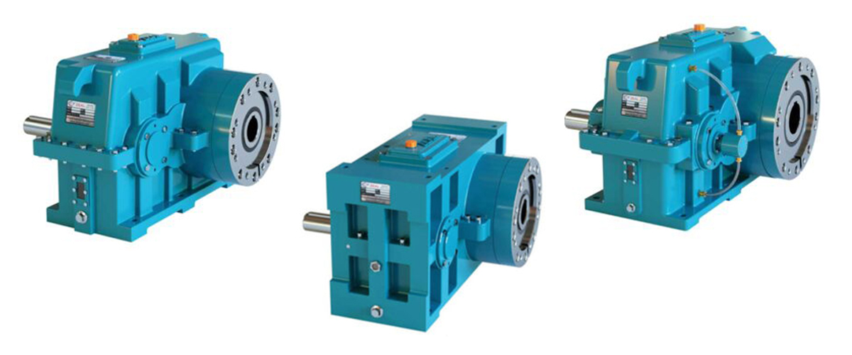
An extruder helical gearbox is a type of mechanical power transmission device specifically designed to be used in extrusion machinery. It is mounted between the drive motor and the extruder screw, and its primary function is to reduce the high-speed rotation of the motor to the precise low-speed, high-torque output that the extruder screw requires.
The word ‘helical’ refers to the type of gear teeth used inside the gearbox. Unlike straight-cut spur gears, helical gears have teeth that are cut at an angle — forming a helix shape along the gear shaft. This design allows multiple teeth to be in contact simultaneously during operation, which distributes the load more evenly, reduces noise, and significantly improves the gearbox’s efficiency and service life.
In simple terms: the motor spins fast but with low torque. The extruder screw needs to spin slowly but with very high torque. The helical gearbox bridges this gap — converting motor power into the exact rotational force the extruder needs.
In simple terms: the motor spins fast but with low torque. The extruder screw needs to spin slowly but with very high torque. The helical gearbox bridges this gap — converting motor power into the exact rotational force the extruder needs.
Quick Definition
Extruder Helical Gearbox = A precision gearbox with helical gear teeth that reduces motor speed and amplifies torque to drive the extruder screw at the correct operating speed and force.
Why is a Helical Gearbox Used in Extruders?
Extrusion is one of the most demanding industrial processes. The extruder screw is required to push raw material — plastic granules, rubber compound, food paste, or similar materials — through a die under enormous pressure. This requires sustained high torque output, often for many hours or even days of continuous operation.
Not every gearbox can handle these conditions. Here is why the helical gearbox is the preferred choice for extrusion applications:
- Higher Load Capacity: The angled helical teeth engage gradually and share the load across multiple contact points at once. This means the gearbox can transmit more torque without gear tooth failure compared to spur gears.
- Smoother and Quieter Operation: Because helical gears mesh gradually rather than all at once, they run much more quietly. In a factory environment, this reduces operator fatigue and indicates more efficient distribution of mechanical stress.
- Greater Efficiency: Helical gearboxes typically operate at 95% to 98% mechanical efficiency, meaning only a negligible fraction lost to the environment as waste heat. This directly lowers your energy costs in long production runs.
- Longer Service Life: The distributed load and smooth operation mean less wear on the gear teeth, bearings, and shafts. A well-maintained extruder helical gearbox can run for decades.
- Vibration-Free Transmission: The gradual engagement of helical teeth produces far less vibration than spur gears, which protects both the gearbox and the extruder screw from premature failure & damage.
Working Principle of an Extruder Helical Gearbox
Understanding the working principle of an extruder helical gearbox requires looking at what happens inside the gearbox from the moment the motor starts to the moment the extruder screw turns. Here is a step-by-step explanation:
Step 1 — Motor Power Input
The electric motor generates rotational energy and delivers it to the gearbox through the input shaft. At this stage, the rotation speed is high — typically 960 RPM to 1,480 RPM depending on the motor — but the torque is relatively low. This high-speed, low-torque input is what the gearbox must transform.
Step 2 — First Stage Gear Reduction
The input shaft is connected to a small helical pinion gear (the driver gear). This small gear meshes with a larger helical gear mounted on an intermediate shaft. Because the driven gear has more teeth than the driving pinion, it rotates slower. This is the first stage of speed reduction and torque multiplication.
The gear ratio at each stage determines how much speed is reduced and how much torque is increased. For example, a 4:1 gear ratio means the output shaft turns four times slower than the input shaft, but delivers four times more torque (minus efficiency losses).
Step 3 — Multiple Reduction Stages
Most extruder helical gearboxes use two or three stages of gear reduction to achieve the required output speed. Each stage passes the power through another pair of helical gears with an increasingly larger gear ratio. By the time the power has passed through all stages, the speed may have been reduced from 1,450 RPM at the input to as low as 15 to 150 RPM at the output, depending on the application requirements.
Step 4 — Torque Amplification and Output
As speed is reduced through each gear stage, torque increases proportionally (according to the gear ratio). The final output shaft of the gearbox therefore delivers very high torque at low speed — exactly what the extruder screw needs to push material through the barrel. The output shaft is directly coupled to the extruder screw through a thrust bearing assembly that also absorbs the enormous axial forces generated during extrusion.
Step 5 — Lubrication System
Throughout this entire process, a lubrication system ensures that all helical gear surfaces and bearings are continuously coated with oil. Many extruder helical gearboxes use a splash lubrication system where the rotating gears pick up oil from the sump and distribute it across all meshing surfaces. Larger units may use a forced-feed lubrication pump for even more reliable oil distribution. This continuous lubrication is critical — without it, the gear surfaces would overheat and fail within minutes.
Step 6 — Heat Dissipation
Despite the high efficiency of helical gears, some heat is generated during operation. The gearbox housing — typically made from cast iron or fabricated steel — dissipates this heat to the surrounding environment. Some high-power extruder gearboxes are fitted with external cooling coils or a heat exchanger to maintain optimal oil temperature during extended operation.
Working Principle Summary
Motor input (high speed, low torque)
–> Stage 1 Helical Gear Reduction
–> Stage 2 Helical Gear Reduction
–> Stage 3 Helical Gear Reduction (if applicable)
–> Output shaft (low speed, very high torque)
–> Extruder screw driven at precise operating speed
Key Components and Their Functions
A well-engineered extruder helical gearbox is made up of several precision-machined components. Understanding each one helps you diagnose issues and make informed maintenance decisions.
| Component | Function |
|---|---|
| Input Shaft | Receives rotational power from the motor; transmits it to the first-stage drive gear |
| Helical Pinion Gears | Small drive gears cut with angled teeth; initiate speed reduction at each stage |
| Helical Wheel Gears | Larger driven gears that mesh with pinions; amplify torque at each reduction stage |
| Intermediate Shafts | Carry gears between input and output stages; supported by precision bearings on both ends |
| Output Shaft | Final shaft that delivers high-torque, low-speed rotation directly to the extruder screw |
| Thrust Bearing Assembly | Absorbs the high axial (thrust) forces generated as the screw pushes material forward |
| Gearbox Housing | Rigid cast iron or fabricated steel enclosure that holds all components in alignment |
| Lubrication System | Ensures continuous oil coverage on all gear teeth and bearing surfaces to prevent wear |
| Seal Assemblies | Prevent oil leakage at shaft entry and exit points; keep contaminants out of the gearbox |
| Cooling System | Manages operating temperature via fins on the housing or an external oil cooler |
Types of Extruder Helical Gearboxes
Not all extruder helical gearboxes are the same. They are manufactured in different configurations to suit different types of extruders and applications. The main types are:
Single Screw Extruder Gearbox
Designed for single-screw extrusion machines, which are the most common type in plastic pipe, film, cable, and profile extrusion. These gearboxes typically feature a single high-capacity output shaft with a large thrust bearing. They are available in a wide range of gear ratios and torque ratings to match different screw diameters and materials.
Twin Screw Extruder Gearbox
Used in twin-screw extruders, which are common in compounding, masterbatch production, and food processing. These gearboxes have two parallel output shafts — one for each screw — and must maintain precise synchronization between the two shafts. They are mechanically more complex and are typically used where mixing, compounding, or devolatilization is required.
Co-Rotating vs Counter-Rotating
Twin screw extruder gearboxes are further classified based on screw rotation direction. Co-rotating gearboxes drive both screws in the same direction, which is ideal for compounding and mixing applications. Counter-rotating gearboxes drive the screws in opposite directions, which is preferred for PVC pipe and profile extrusion due to the high pressure they generate.
Technical Specifications at a Glance
When evaluating or purchasing an extruder helical gearbox, these are the key technical parameters you should review:
| Parameter | Typical Range | Importance |
| Output Torque | 500 Nm to 250,000 Nm | Must match extruder screw load |
| Gear Ratio | 5:1 to 100:1 | Determines output speed from motor RPM |
| Input Speed | 960 to 1,500 RPM | Matches standard motor speeds |
| Output Speed | 15 to 300 RPM | Matched to material and screw diameter |
| Mechanical Efficiency | 95% to 98% | Impacts energy consumption |
| Service Factor | 1.25 to 2.0 | Indicates shock load capacity |
| Lubrication Type | Splash or forced-feed | Critical for continuous duty |
| Thrust Bearing Capacity | Application specific | Must withstand axial screw forces |
| Material of Gears | Case-hardened alloy steel | Ensures wear resistance and strength |
| Housing Material | Cast iron / fabricated steel | Ensures rigidity and heat dissipation |
Our Extruder Helical Gearbox Solution
If you are looking for a reliable, high-performance extruder helical gearbox for your production line, our range of precision-engineered extruder gearboxes is built to deliver consistent performance under the most demanding operating conditions.
Our extruder helical gearboxes are designed and manufactured to meet the exact torque, speed, and reliability requirements of single-screw and twin-screw extrusion applications across plastic, rubber, cable, pipe, and food processing industries.
Why Choose Our Extruder Helical Gearbox?
- Case-Hardened Alloy Steel Gears: All gear sets are manufactured from high-grade alloy steel, precision hobbed, and case-hardened for maximum surface hardness and long service life.
- High Efficiency Design: Our gearboxes operate at up to 98% mechanical efficiency, helping you reduce energy consumption and operating costs.
- Heavy-Duty Thrust Bearing: Each gearbox is fitted with a high-capacity thrust bearing specifically rated for the axial load generated by your extruder screw.
- Customizable Gear Ratios: We offer a wide range of standard and custom gear ratios to precisely match your motor speed and required screw speed.
- Proven Reliability: Our gearboxes are engineered for continuous duty operation in 24/7 production environments.
- Full Technical Support: Our engineering team provides installation guidance, alignment support, and after-sales service.
Contact us today to discuss your extruder gearbox requirements and receive a customized technical recommendation for your application.
Frequently Asked Questions (FAQs)
Q1. What is the difference between a helical gearbox and a spur gearbox for extruders?
A helical gearbox uses gears with angled (helical) teeth that engage gradually, distributing the load across multiple teeth simultaneously. This results in smoother operation, lower noise, higher load capacity, and greater efficiency compared to spur gears, which have straight teeth that engage all at once and generate more noise and vibration. For continuous-duty extrusion applications, helical gearboxes are strongly preferred.
Q2. How do I select the right gear ratio for my extruder gearbox?
The correct gear ratio depends on your motor speed and the required extruder screw speed. Divide your motor RPM by your required output RPM to get the needed gear ratio. For example, if your motor runs at 1,450 RPM and your screw requires 50 RPM, you need a gear ratio of 29:1. Always allow a margin for start-up torque and variable loads by selecting a gearbox with a service factor of at least 1.50 above the calculated requirement. It depends on type of load like uniform, shock or heavy shock load.
Q3. How often should an extruder helical gearbox be serviced?
For most applications, a full oil change is recommended every 3,000 to 5,000 operating hours or every 12 months, whichever comes first. Bearing inspections should be carried out every 6 months. Gear tooth wear checks and alignment verification are recommended annually. Always follow the manufacturer’s maintenance schedule provided with your specific gearbox model.
Q4. What causes noise or vibration in an extruder helical gearbox?
Common causes include gear tooth wear due to inadequate lubrication, bearing failure from overloading or lack of maintenance, misalignment between the motor shaft and gearbox input shaft, oil contamination, or operating the gearbox beyond its rated torque capacity. If you notice unusual noise or vibration, stop the machine and inspect immediately to prevent major damage.
Q5. Can an extruder helical gearbox be repaired, or does it need to be replaced?
In many cases, an extruder helical gearbox can be overhauled and repaired by replacing worn gears, bearings, seals, and shafts. A professional gearbox repair and rebuild service can restore the unit to near-original performance at a fraction of the replacement cost. However, if the gear housing is cracked or the gear teeth are severely damaged across multiple stages, full replacement is the more economical long-term choice.
Conclusion
An extruder helical gearbox is far more than a mechanical component — it is the heart of your extrusion line. It determines the speed, torque, reliability, and efficiency of everything your machine produces. Understanding how it works, knowing its key components, and recognizing early warning signs of wear can save you from costly breakdowns and lost production time.
The helical gear design offers clear advantages over other gear types for extrusion applications: higher load capacity, smoother operation, greater efficiency, and a significantly longer service life. Whether you operate a plastic pipe plant, a rubber profile line, a cable extrusion facility, or a food processing unit, investing in the right extruder helical gearbox is one of the most important decisions you can make for your production line.
